a vector look at the currents into the op amp virtual ground
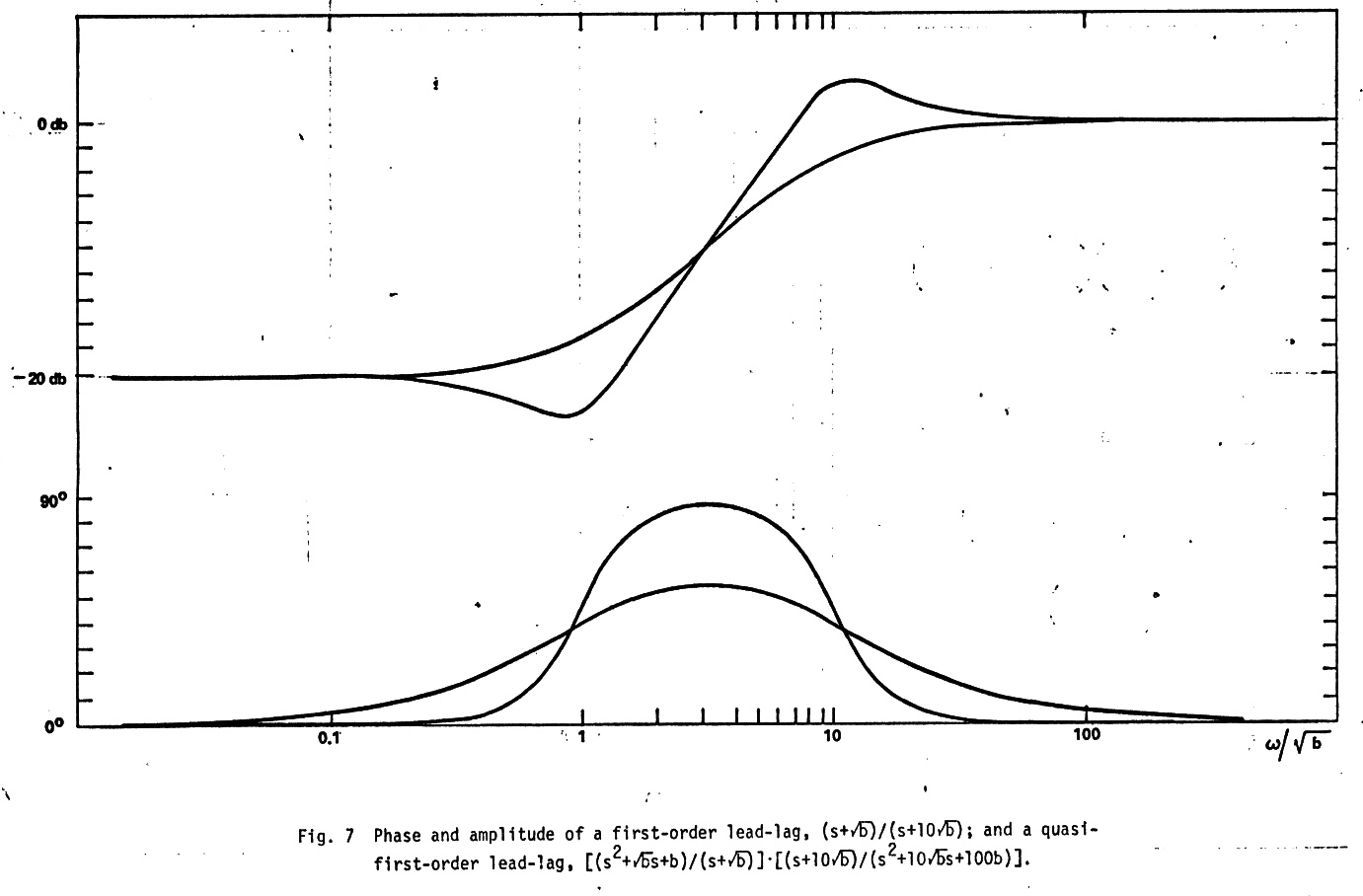
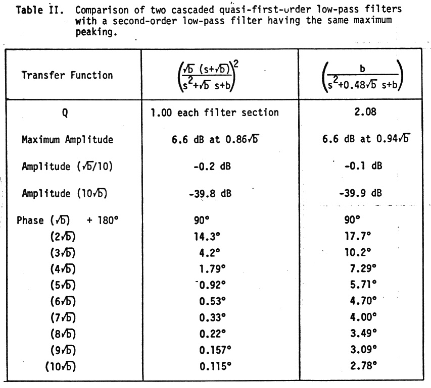
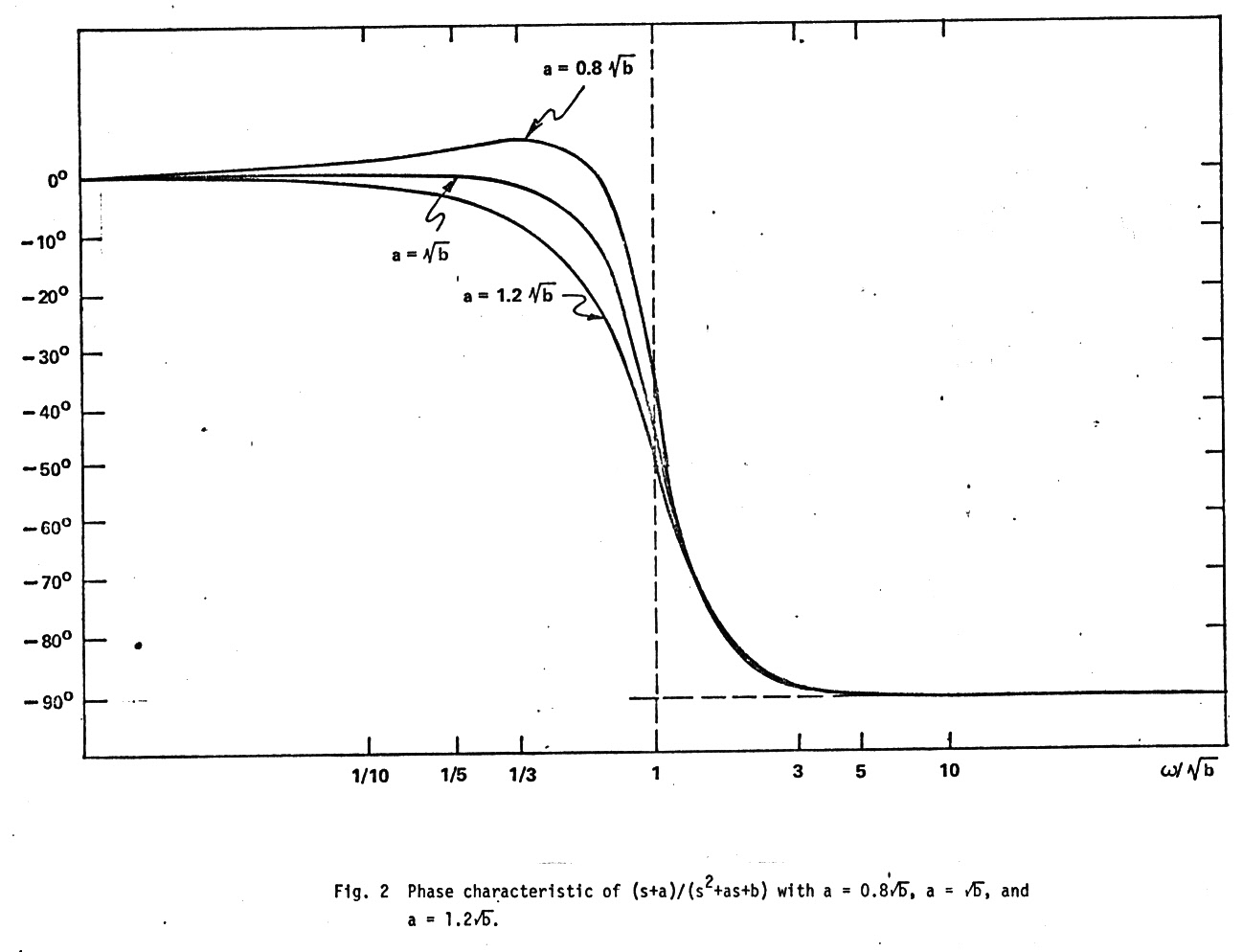
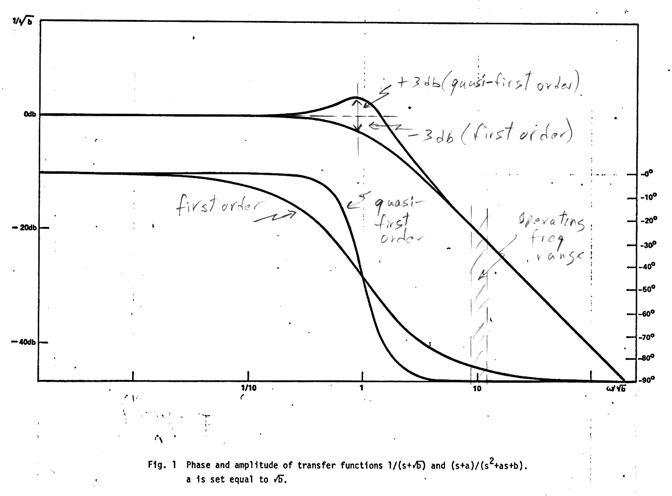
There have been thousands and thousands of filters invented, but I invented a new one (I think) in the early 1970s. A variation on the first order filter that I named a quasi-first order filter, a new class of filters with very stable asymptotic phase characteristics. A quasi first order low pass filter has an amplitude response similar to a first order low pass, but instead of being down 3db at the pole like a first order filter, something all EE students learn in the first week of circuit theory, it is up 3db (see fig 1). Surprisingly this very small amplitude difference makes a big difference in shape of the phase characteristic away from the pole. The phase of a quasi-first order filter approaches its phase asymptotes much more rapidly than a first order filter (see fig 1), and that was its attraction because we had an unusual application where the stability of the phase of an integrator/noise filter was a critical concern.
Accelerometer readout
The application
was the readout of the precession angle of a gyro based accelerometer in
an inertial guidance system. This type of accelerometer is an unbalanced
gyro (PIGA)
that precesses at a rate proportional to acceleration, so according to
newton's gyroscopic laws the gyro performs an integration with the gyroscopic
precession angle being a measure of the instantaneous velocity
of the rocket. To read out this angle this type of rotating gyroscopic
accelerometer incorporated a resolver spanning the rotor to stator gap.
A resolver
is a rotating transformer whose coupling varies as the sine and cosine
of the mechanical angle. By exciting its two rotor windings in spacial
quadrature with carriers in time quadrature, the resolver stator output
is a nominally constant amplitude carrier whose phase tracks the mechanical
angle. As the mechanical angle of the resolver varied from 0 to 360 degrees,
the phase of the output carrier tracked it varying 0 to 360 degrees electrical,
or one full cycle.
To filter noise and harmonics and to adjust the gain we needed a simple op amp filter circuit to insert between the resolver and the phase lock loop that was going to track and digitize the phase. Clearly since the phase of the carrier was the output of a very high precision inertial instrument, we needed a filter whose phase shift was going to be very stable. And if it was a predictable value that would be a bonus. The maximum precession rate of gyroscopic accelerometers is relatively low, so that meant the filter was only going to see a narrow range of frequencies centered on the carrier frequency, thus we need only be concerned about the phase of the filter in this narrow frequency range.
First order filter soft phase characteristic
An op amp
with parallel RC in the feedback path (see sketch below) implements a simple
first order low pass filter. The idea was to operate the filter in down
slope region away from the pole, where the feedback capacitor dominates
so it acts pretty much like an integrator. The question was how far below
the carrier frequency was it necessary to place the pole (1/RC) to get
good phase stability, and here is where the numbers of a first order filter
are bad. Even operating a factor of ten away from the pole the phase shift
of a first order filter is still 5.71 degrees [inverse tan(0.1)] from its
phase asymptote, in this case a 90 degree lag. The fact is that the phase
characteristic of all first order filters, low pass and high pass, is soft,
the phase approaching its phase asymptotes quite slowly.
Inventing the quasi-first order filter
A look at
the feedback currents into the virtual ground of the op amp (see sketch
below) shows the problem. In a first order low pass filter the real current
through the feedback biasing resistor is in quadrature with current
from the capacitor, which leads the output voltage by 90 degrees. So the
first thought was to bisect the feedback resistor and hang a capacitor
from there to ground. If I reduced the voltage across the resistor into
the virtual ground by about an order of magnitude, I was expecting about
a factor of ten improvement, the 5.71 degree phase hang off dropping to
about 0.57 degrees. When the circuit was analyzed in more detail, however,
I found the improvement in the phase hang off was not a factor of 10 as
I had expected, but a factor of 100! Beside the amplitude reduction the
capacitor to ground introduces about an 84 degree lag into the bias current
with the result that component variations that would typically cause a
phase variation now mostly make a small amplitude variations, but that
is Ok in our application, because the tracking phase lock loop isn't sensitive
to the amplitude of the carrier.
I had found that just adding a bypass cap into the resistive feedback path can have a dramatic effect of the shape of the filter phase response sharpening it up so it heads to the phase asymptotes quickly. This results in the phase hang off at x10 the pole frequency being reduced by a factor of 100 from 5.71 degrees (84.29 degrees) to only 0.057 degrees (89.943 degrees). That means any phase variations due to component variations are similarly reduced. But how much low frequency peaking was this bypass capacitor introducing?
The second big surprise was this huge improvement in the phase response could be obtained with only a minor effect of the magnitude of the filter. I choose to size the bypass capacitor so that the amplitude characteristic was approximately first order (hence 'quasi-first order') with the amplitude change occurring only near the pole, the gain up 3 db (x 1.41) vs down 3 db (x .707) in a first order filter. And as a bonus how to pick the value of the bypass cap could be seen by inspection. Just set the bias path pole (RC = R/4 x 4C) to be the same as the main RC pole.
Paper history
I wrote this
all up in gory detail for several IEEE circuit journals in 1973 (!), but
not explaining in detail the need for the filter because it was a military
application. I got a reply that some reviewers liked the paper, but they
wanted confirming phase measurements to be made with real op amps, and
the paper to be shortened. Our lab owned a high precision phase meter,
and I did the phase tests and confirmed that the phase was indeed very
accurate and stable, but I got so tired of working on this 21 page overwritten
paper that I never resubmitted manuscript. (I was a working engineer, not
an academic engineer who writes papers.)
A google search turns up nothing like it, which is not too surprising since in only a tiny fraction of filters is the phase shift of the filter a concern. So before I shuttle off this earth, I've decided to 'self publish' on my home page this idea, a sketch showing intuitively how it works, a summary of the mathematical derivation, and I am including scans of most figures from the paper from over 40 years ago that show the general equations of other filters of this quasi-first order class of which there are many. It really does work, it was incorporated into the design of our inertial guidance system.
Quasi-first order phase vs first order phase
As my sketches
below show a simple active first order low pass filter can be converted
into a quasi-first order low pass just by dividing resistive feedback resistor
and bypassing the center point to ground with a capacitor. To achieve the
quasi-first order +3db rise at the pole the bypass capacitor is set at
4C. (From the general low pass equation c is set equal to a and a to sqrt{b}).
Operated as an integrator at x10 the pole frequency (w = 1/RC) the first
order filter is 5.71 degrees from its ideal 90 degree (lag) phase asymptote,
whereas the quasi-first order with its tapped resistive feedback path is
only 0.057 degree from its ideal 90 degree (lag) phase asymptote.
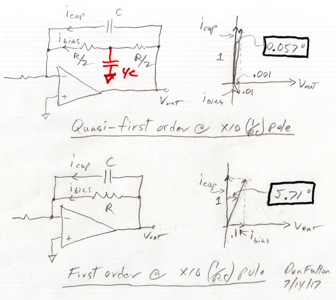
The easiest way to understand what is going on is to draw the two components of current (icap and ibias) into the op amp virtual ground as vectors using the op amp output voltage (Vout) as a phase reference.
My sketches below show a quasi-first order filter formed by adding AC bypass capacitor (4C) to the bias path of a conventional active low pass filter. This reduces the phase hang off from the asymptote by a factor of x100 [5.71 degree => 0.057 degree]! x10 is due to amplitude reduction in ibias and x10 due to a phase shift in ibias, such that ibias is mostly in phase with icap rather than in quadrature with it. In other words phase shifting ibias tends to make any variations in it, say due to component or temperature variations, to result in amplitude variations not phase variations.
a vector look at the currents into the op amp virtual ground
First order circuit
The first
order filter is 5.71 degrees away from its phase asymptote because the
current through the cap at x10 pole frequency (1/RC) is x10 larger in magnitude
than the bias current through the resistor. As the vector diagram shows
the two currents into the virtual ground are in quadrature, the
resistive current (0.1) in phase with Vout and the capacitor current (1)
leads Vout by 90 degrees. The inverse tangent of 0.1 is 5.71 degrees.
Quasi-first order circuit
Splitting
R into R/2 and R/2 in series and AC bypassing the center point to ground
obviously has no effect on the current through the capacitor, which remains
at amplitude 1. Setting the bypass capacitor at 4C sets the pole in the
bias path to be the same as in the main feedback path (1/RC) and gives
us the quasi-first order amplitude shape. The short hand way of seeing
how to set the capacitor is a capacitor normally breaks with the resistance
it 'sees', which in this case is R/2 in parallel with R/2 or R/4, hence
the capacitor is set equal to 4C making the pole in the bias path is 1/(4C
x R/4) = 1/RC.
If you were to look with a scope at the point between the two bias resistors and switch the 4C bypass capacitor in/out, what would you see, assuming sinewave excitation at [x10 (1/RC)] or ten times the pole frequency? The answer is that the voltage amplitude will drop by a factor of ten when the capacitor is switched in, thus the amplitude of ibias into the virtual ground drops by a factor of ten from 0.1 to 0.01. This amplitude effect alone would decrease the phase hang off from the asymptote from 5.71 degrees to 0.571 degrees (max).
But switching in the 4C bypass capacitor also introduces a lag into the voltage in this path, about an 84 degree lag since we are x10 above the pole. But notice in the sketch the effect of this phase lag. The bias current is now lagging Vout by 84 degrees whereas the capacitor current leads Vout by 90 degrees. In other words the bias current (here about 1 % of Icap) rather than primarily causing a 0.57 degree = [inverse tan (.01)] phase shift in the sinewave at Vout is now primarily causing an amplitude increase (about 1%) in the sinewave at Vout. Resolving the vectors shows that about 10% of the 0.01 bias current, or 0.001, is in quadrature with capacitive current, and this explains the phase hang off of 0.057 degree = [inverse tan (.001)].
The trickStarting with the equation
This is the essential 'trick' of the quasi-first order class of filters. By adjusting the phase of the current in the bias path so it ends up at the virtual ground mainly in phase with the capacitor current rather than in quadrature with it, it converts any variation in this bias current, say due to component temperature or tolerance variations, from causing a phase change to causing (mostly) an amplitude change. In other words the phase of the filter has been made more accurate and stable at the expense of the amplitude.
Replace a first order [H(s) = 1/(s +a)] with [H(s) = (s +a)/(s^2 + as +
b)]
where a = sqrt{b}
Add a zero
At the frequency
where the denominator breaks into a second order roll off [w = sqrt{b}]
place a zero [w = a] converting the overall response to a (quasi) first
order roll off with the pole at [w = a = sqrt{b}]. Write the equation for
the phase away from the pole by using the following expansion formulas
(for small z and small x).
tan^-1 (z) = z - (1/3) z^3 + (1/5) z^5...
1/(1-x) = 1 + x + x^2
(Note this is done is some detail in the paper, here I am simply summarizing the results from the paper.)
Let's start with the general quasi-first order low pass filter transfer function. The first term is the phase of the numerator and second term the phase of the denominator.
H(s) = (s+c)/(s^2 + as + b)
phase = tan^-1 (w/c) - tan^-1 (aw/(b - w^2))
after some manipulation applying the expansion formulas and for w >>c and w >> sqrt{b} we get
phase = -pi/2 - c/w + a/w + higher order terms
clearly to get the num and den first order phase terms to cancel set (c = a), and for a quasi-first order phase characteristic set a = sqrt{b}
H(s) = (s+a)/(s^2 + as + b) ==> (s+sqrt{b})/(s^2 + sqrt{b}s + b)
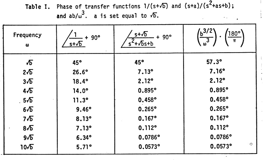
This gives the desired rapid approach of the phase to the phase asymptote. Below is the hang off from the asymptote
w = sqrt{b}
45 degree
w = 3 x sqrt{b}
2.12 degree
w = 5 x sqrt{b}
0.458 degree
w = 10 x sqrt{b}
0.0573 degree
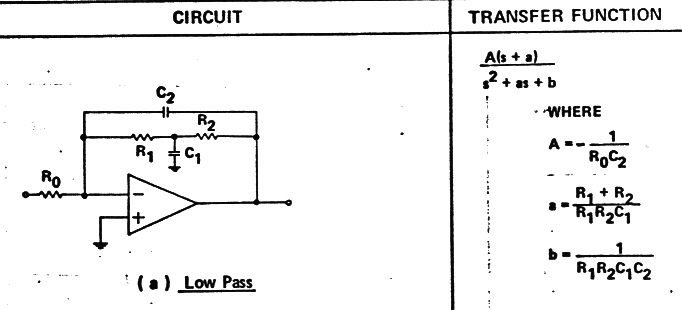
General equation for quasi-first order low passTo relate the above general expression to my pencil sketch above substitute R1 = R2 = R/2 and C1 = 4 C2, so we get
a = 2(R/2)C2/(R/2 x R/2 x 4C2 x C2) = RC2/(RC2)^2 = 1/RC2
b=1/(R/2 x R/2 x 4C2 x C2) = 1/(RC2)^2
Hence
a = sqrt{b} checks
Note above shows the only amplitude 'penalty' in a quasi-first order filter to get its desired rapid phase approach to the asymptote is a small peaking of 3db (x1.41) near the pole, otherwise it has a normal first order amplidude response. In our aerospace application this allowed it to function (at w = x10 pole freq) as a high freq noise filter and integrator introducing a predictable 90 degree lag.
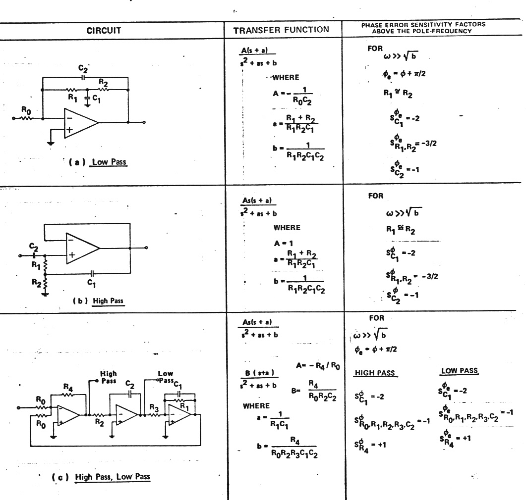
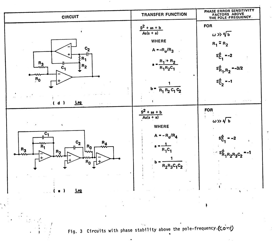
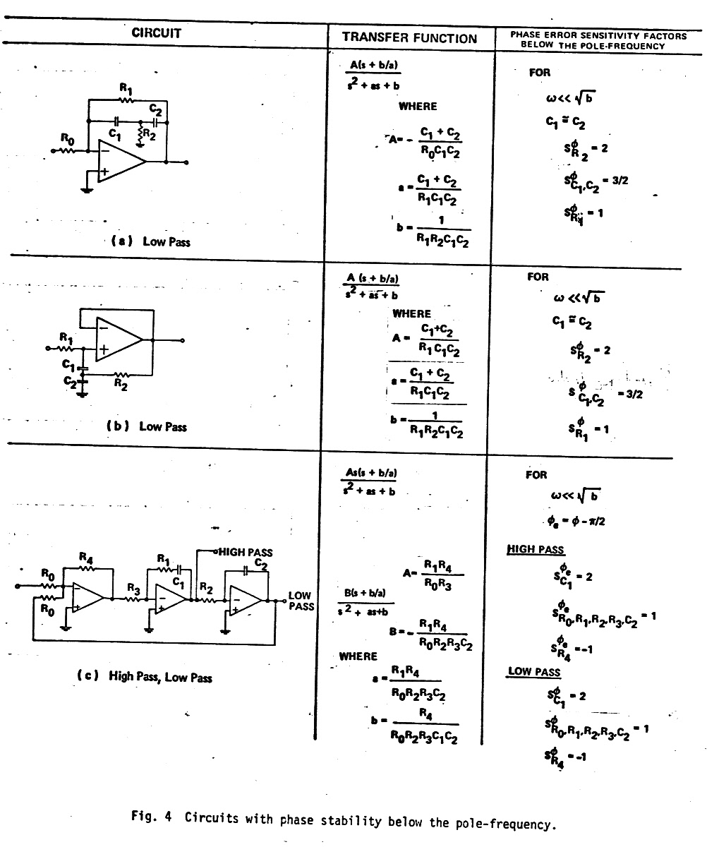
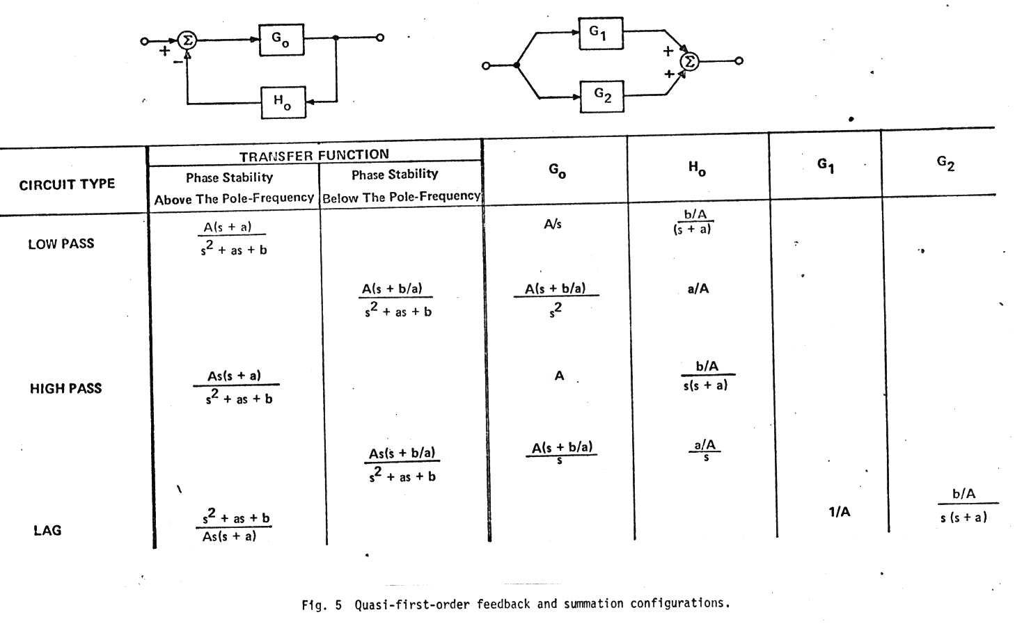
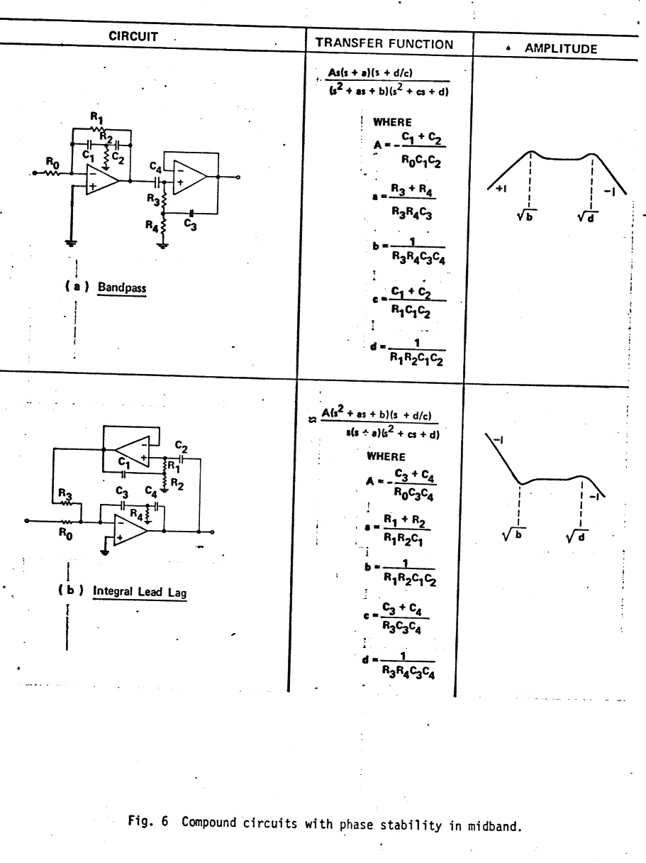
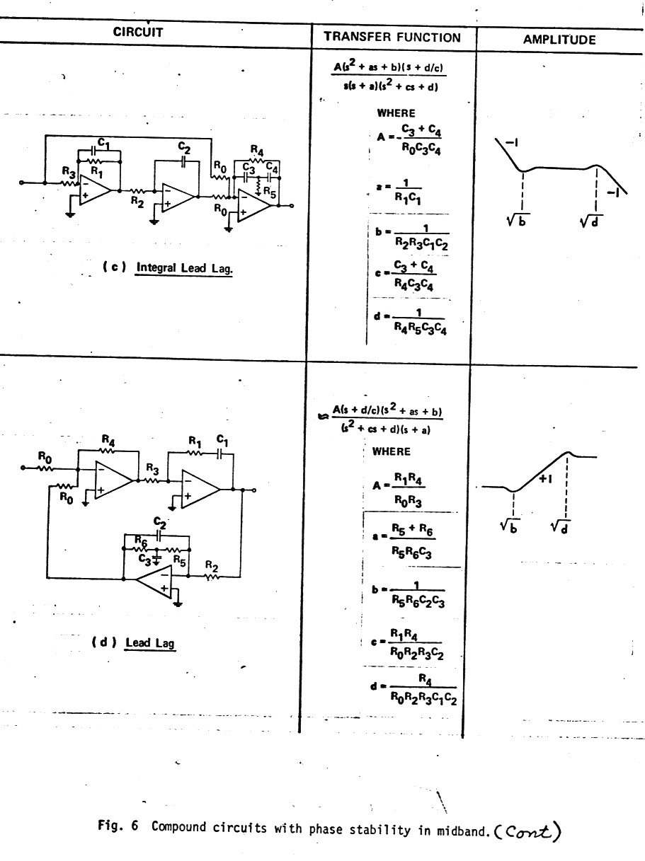
Bunch of potential quasi-first order filters
Below are
a bunch of filter circuits with their transfer functions that can be set
up to have a quasi-first order response. Note they all have a single order
zero (or pole) that can modify the second order order term. (The quality
of these figures leaves something to be desired, but this is what has survived
in my notes from my 1973 paper of 44 years ago!)
..