Inside view of Tesla Model 3 inverter in cylindrical
case
My related essay on 'Hydrogen fuel cell car' is here
Go to homepage
New
generation of economical 200+ mile electric cars
Tesla
Model 3
GM
Bolt EV
Leaf
vs Volt drive train mini-tutorial
Toyota/Ford/Honda/Lexus
hybrid block diagram
VW
introduces a very different hybrid architecture
Batteries
Nickel
Metal Hydride (NiMH) batteries
Prius
NiMH battery
Tesla
battery low temperature problem
Battery
power out vs load resistance
Lithium
ion
Lithium
ion comparison to NiMH
Comparison
of Volt and Leaf lithium battery thermal management
Battery
coolant problems
quasi-electric GM Volt
GM
Volt lithium ion battery
GM
Volt revealed to be a hybrid!
Toyota
Prius plug-in hybrid 2012
quasi-electric
Fisker Karma sedan
Classic
video --- Karma has the world's worst screen car controller
Tesla Motors lithium ion pure electric cars
Tesla
2 seat roadster
Tesla
Model S sedan -- 300 mile range
Comparing
electric car motors --- Fisker Karma vs Tesla Model S
Nissan
Leaf electric
Leaf
99 mpg EPA sticker
Ford
Focus electric
Coda
electric
UQM
motor + controller supplier
EV-1
specs
Mini-Cooper
electric
Mitsubishi
MIEV electric car
Electric
car batteries and range
Desiging an electric
car
Motor
Electrics
PM => induction
Motor
speed comparisons
Inverter/boost
Why
a booster converter?
IGBT
transistor modules
Comparing
hybrid ? non-hybrid siblings
Toyota hybrid technology
Toyota
gen III 2010 Prius specs
Toyota
gen III circuit sketch
Ford 2010 Fusion hybrid
Ford
2013 Fusion hybrid
Plug-in hybrids
Ford
2013 Fusion Energi plug-in hybrid
Hybrid architecture
Mysteries
of the 'power splitter'
Works
like a three winding transformer
Toyota's
power splitter formula
Local
power loop!
Overdrive
New Hyundai
hybrid architecture
Chinese BYD F3DM
electric
Electric
car charge standard --- SAE J1772
Simple
built-in charger
Wireless
charger
MPGe EPA standard
Wind resistance hp
** My
personal contributions to hybrid/electric technology
Formula E (electric)
racing (Nov 2014)
Appendix
Fire
in Boeing 787 (Dreamliner) lithium ion batteries (Jan 2013)
Reference
Wind resistance
13 hp / 9.7 kw @ 55 mph
17 hp / 12.6 kw @ 60 mph
40 hp / 29.6 kw @ 80 mph
57 hp /42.2 kw @ 90 mph (Nissan Leaf top speed)
79 hp /58.5 kw @ 100 mph (GM Volt top speed)
---------------------------------------------------------------------------------------------------------------------
As a retired
engineer, I'm interested in the developing technology of hybrid and electric
cars, and what I learn goes into this essay.
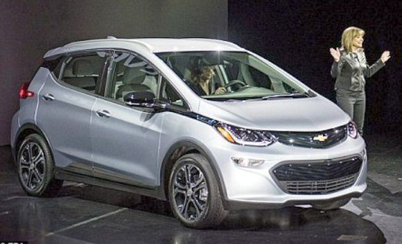
New
generation of economical 200+ mile electric cars (4/16)
Electric cars
for the mass market, priced around 35k and with batteries big enough for
200+ range, are scheduled to begin hitting the market in 2016/17. These
cars promise more than double the 100 mile range of the first generation
electric cars, yet priced for the mass market. The manufs in 2016 are beating
the drums, but hard specs at this point are very few. While these 2nd gen
electric cars have about double the range of the 1st gen cars, 200 miles
range is still limiting and from photos the size of the car you get
for 35+k looks somewhat small.
Tesla Model 3 (7/7/17)
(7/28/17) (12/2/17)
(12/2/17)
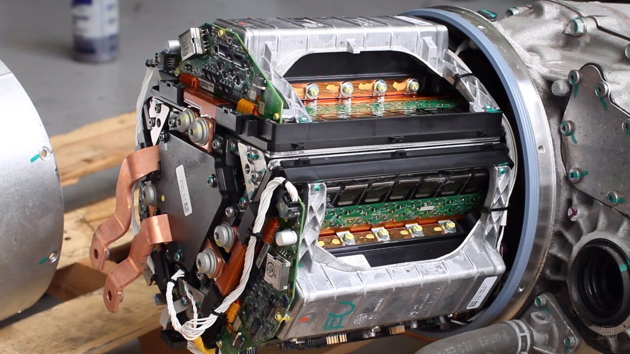
The
inverter, which converts DC of the battery to variable 3 phase AC for the
induction motor, is packaged opposite the motor in a cyclindrical case
about the same size as the motor. Looks nice and clean from outside, but
packaging a high power and control electronics in a cylindrical case...
This can't be simple. A hacker video on Youtube took the case off the Tesla
Model 3 inverter giving us a glimpse of the inside.
Inside view of Tesla Model 3 inverter in cylindrical
case
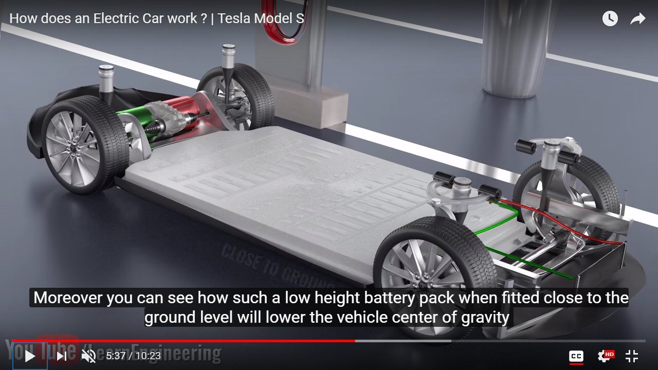
Details of the Model 3 drive train and battery pack
(12/1/17)
With Model
3 in the hands of customers (as of this date all Tesla employees), one
guy who bought an early prototype and did a tear down, and a detailed video
details of the battery pack are coming out.
https://www.youtube.com/watch?v=3SAxXUIre28
The battery pack is speced at 375 V (probably close to 400V fully changed). Prototype model 3 battery packs used the existing 1865 cell, but production cars will use the slightly larger 2170 cell. The cells are arranged in series parallel groups. Each cells is 3.6 to 3.7V (nominal) and has a rating of about 3.3 Ahr (12 wh), which implies a 100 kwh battery pack must have a little over 8,000 cells and a 75 kwh battery pack a little over 6,000 cells. Tear downs show each cell coupled in through a small fuse. The video shows each row of cells is touching a cooling band with circulating glycol that brings the heat to a radiator in the front of the car.
While not shown in the video I am pretty sure the inverter and motor must be cooled too, very likely by the same same glycol system used for the battery. The reason they probably share the same cooling loop is that post discussions say there is an algorithm where the motor can be used to generate heat without torque and that this is needed if the ambient is low because cold cells don't charge well.
Images from Tesla model 3 video
These images
are from the video above. This video was apparently not produced by Tesla,
but its images agree with model 3 photos.
 .
. 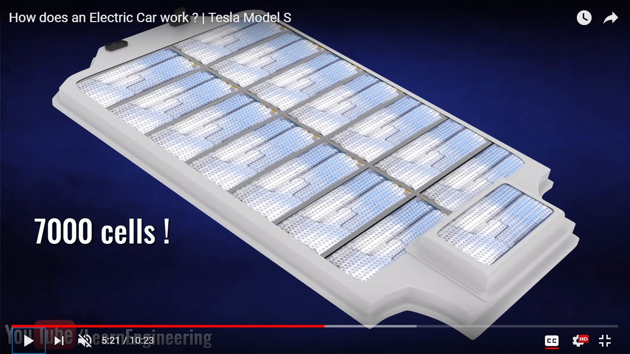
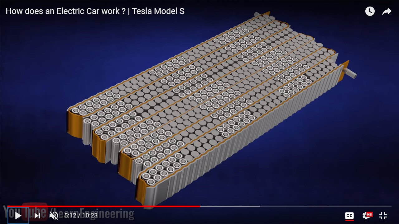
(left) battery pack module showing glycol cooling band
(module -- 36 cells x 14 row = 504 cells)
(right) battery pack (15 modules x 504 cells = 7,560 cells)
..
 .
. 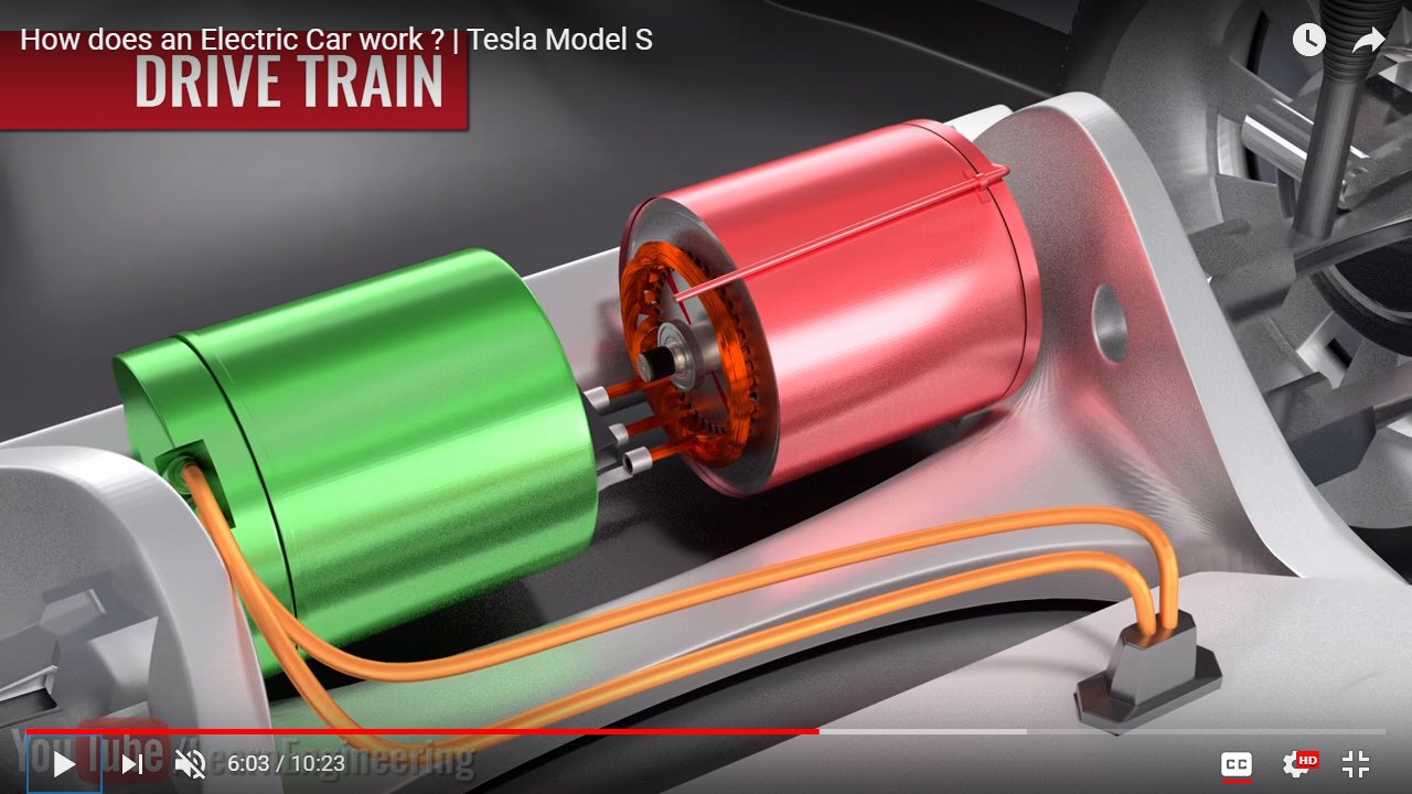
rear wheel drive train --- induction motor (red), inverter (green)
Tesla model 3 inverter transistors
It's very hard to get data
online about the transistors used in inverter of the model 3. It appears
that the inverter is coupled directly to the battery pack and that the
battery pack voltage is 375 VDC spec. But due to ESR (value not known)
the battery voltage sags (at the terminals ) when the battery is outputing
high power. Say the battery sags to 300V (could sag more). One reference
shows the car rated power at 191kw (258 hp), but higher power versions
show power output ratings of 300 kw. Working the numbers this shows the
current at these peak power levels is wicked high [300kw/300V = 1,000 amps,
191kw/300v = 636 amps]. The forward voltage of a power IGBT is typically
about 2.1V [IXYS IXXH150N60C3 spec for a 150A, 600V TO-247 fast switching
IGBT is 2.1V 25C, 2.6V 150C static]. Roughly speaking the power output
of the inverter at 1,000 amps is 2,000 watts static (and maybe 3,000+ watts
when switching losses are included), so the inverter needs a lot of cooling.
http://ixapps.ixys.com/DataSheet/DS100558A%28IXXH150N60C3%29.pdf
Surprisingly photos appear to show the model 3 does not use packaged igbt module, but discrete transistors (maybe TO-247s). This means considerable assembly at Tesla as each of the transistors has to be electrically isolated and reliably coupled to a heat sink (through the insulator). One photo (see below) shows a PC board (supposedly from a model 3) with what looks like 28 = 7 x 4 TO-247s. There could be (and likely is) more than one PC board like this in the inverter to reduce the peak currents in the transistors, PC board traces and to spead out the heat. In other words there are a lot of parallel transistors (maybe 7 or 14 or 21) in each of the six legs of the inverter.
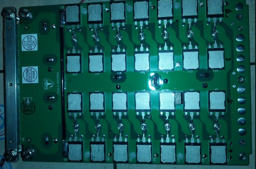
Tesla power PC board (from Tesla model 3 inverter?) with parallel
TO-247 transistors
The
extended rollout of the Model 3 continued today with the delivery of the
first 30 production vehciles. Turns out that all of the first 30 cars have
been sold to employees of Tessla Motors. Whle the base model is 35k the
WP reports if fully equipped with it will run more like 60k. A larger battery
option (310 miles range) is 9k. 2nd generation autopilot is 5k. Full self
drive an extra 3k. To get any color other than black is an extra 1k.
--------------
Tesla Model 3
The headline
in the general press is the Tesla model 3 officially goes on sale today
(7/7/17) with the implication being that deliveries will soon begin as
the first car has rolled off the assembly line. Wikipedia points out that
beginning of its production is a drawn out affair, that there will be an
'official launch' on July 28, where the first 30 owners will take delivery.
Tesla projects production volume will reach 5,000/wk (4th quarter) rising
to 10,000/wk in the second year. Skeptics on the production numbers abound.
So finally the specifications should now be available, or so you would think. Well think again, there is almost no information of the Tesla 3 web site as of today. No info on the battery baseline, the max battery capacity, the motors, or even the weight of the car.
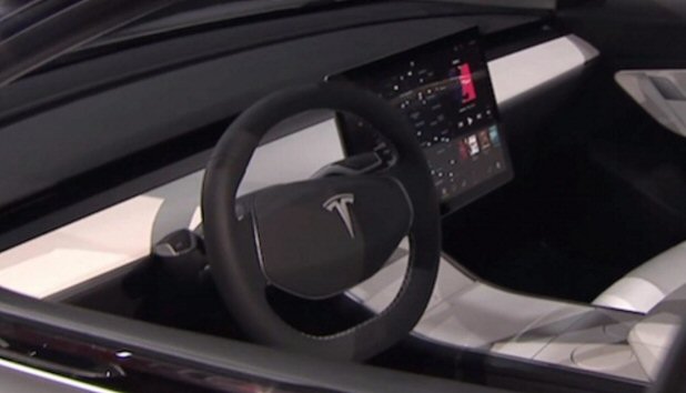
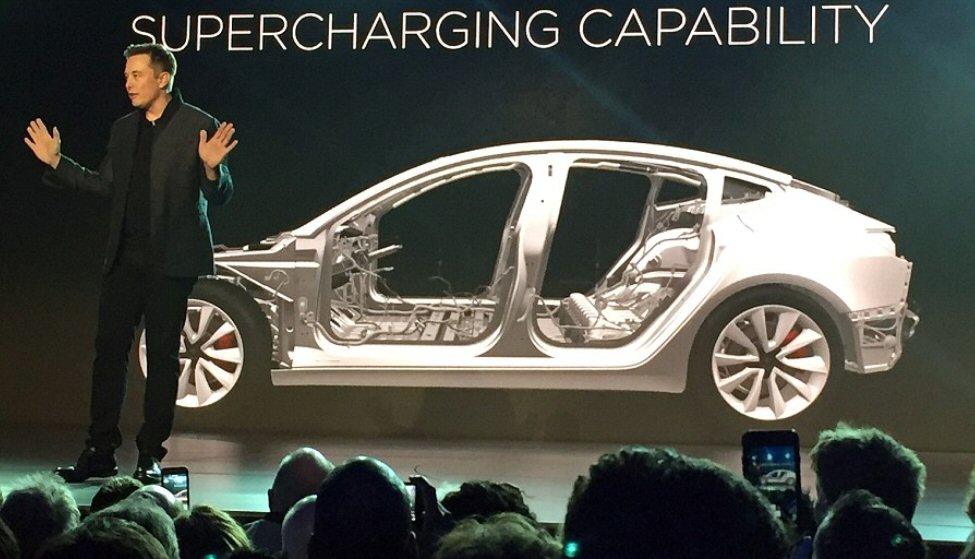
Curiously this is a rear drive car (base model). There are actually three (or four) motor options. In addition to the base model with a double rear motors. There is an all wheel option where one of the rear motor is moved to the front. There is a high performance option with a single motor front and two motors rear. The rear motors here are called high perfromance motors, and the car is speced 2.5 sec (0 to 60) with all three motors. It will come with the full Tesla self drive technology. No longer will the central computer screen supplement the dashboard speedometer etc, in the Model 3 it has replaced them. Photos show the dashboard in front of the driver totally blank. The car is very aerodynamic with a drag coefficient reported to be a very low .21 (much lower than the Bolt). The car supports fast DC charging.
 .
. 
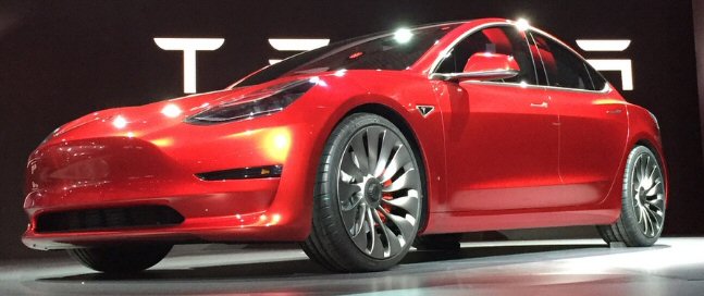
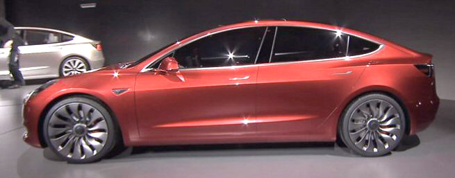
Tesla model 3 high volume production car
Tesla Model 3 (high volume production car) (7/28/17
update)
Price (base mdel)
35k
(35k base without incentives, but 42k with 'av' options) (60k fully equipped)
(long range model) 44k
(9k extra for larger battery)
Range
215 miles
(EPA rated) (> 300 ? mile range for 75 kwh) (vs 238 for Bolt)
(220 to 310 miles) latest spec
Battery (baseline)
53 kwh (est)
(vs 60 kwh for Bolt)
Battery (max)
75 kwh (est)
Musk said in march 2017 there is room for a 75 kwh battery pack in model
3,
so this is probably the kwh of the long range model. scaling from that
220 miles/310 miles x 75 kwh = 53 kwh for base model
Battery cell size
2170
(21 mm dia x 70 mm length)
Wheelbase
113"
(vs 102.4" for the Bolt)
Weight (curb)
3,837 lb
(long range model)
Seating
5 passengers
Controls
15" touchscreen (center)
Accel (0 to 60 mph) 5.6
sec (5.1 sec long range model, heavier (extra 265 lbs), but higher
peak current available from battery)
2.5 sec performance option (three motors)
Top speed
130 mph
Rated hp
258 (191 kw = 545A x 350 VDC) (long range model)
Availability
July 2017 (customer deliveries of long range battery model in late oct
2017)
Battery cell
Tesla model
3 battery will be made up of cylindrical cells like previous Tesla cars,
but larger, it will be the new 2170 cell (21 mm dia x 70 mm length) designed
to be produced in high volume at Tesla Gigafactory in Sparks NV. Tesla
has partnered with Panasonic on the battery. Beyond having a larger form
factor than the existing 18650 battery cell (18 mm dia x 65 mm length),
which is being used in Teslas existing vehicle fleet, the new 2170 lithium-ion
cell boasts a higher energy density by as much as 30%. The cells
are designed to support fast charging, which means they must have a low
ESR.
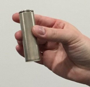
2170 Li-ion cell for Tesla Model 3 battery pack
 .
. 
Musk introducing '35k' Tesla Model 3 on 3/31/16
The Bolt with its 102.4 inch wheelbase is a little smaller than the Volt (105.7 inches). It has over three times the battery capacity of the Volt (60 kwh vs 18.4 kwh 2nd gen), which means additional battery weight of 600-700 lbs, of course this is to be traded off vs the removal of the gasoline engine. The curb weight of the Volt is 3,794 lb, so if prelim Bolt weight of 3,580 lb is right, it is a couple of hundred pounds lighter than the Volt. The Bolt is a lot smaller than the announced, but still far from production (available 2017), low cost model 3 (35k) from Tesla, which is estimated to have 113 inch wheelbase.
The currently available (expensive 76k - 85k) Tesla Model S, highly rated by Consumers Guide with more than 100,000 sold since 2012, is bigger still, a full size car with a 116.5 inch wheelbase. 70 kwh (240 miles) and 85 kwh (265 miles) are the baseline battery capacities in the Model S, but for mucho extra bucks a 100 kwh battery can be squeezed in increasing the EPA range to more than 300 miles. The model S is a heavy, high performance car, with an 85 kwh battery it has a curb weight of almost 5,000 lb.
Price
37.5k
Range
238 mile range (as measured by EPA)
Battery
60 kwh
(flat battery pack filling the underside of car) (960 lbs)
Wheelbase
102.4"
(looks pretty small in pictures, sort of a four door hatchback) (164" long,
3,580 lb)
Accel (0 to 60 mph) <
7 sec
(91 mph top speed)
Availability
2016 (late)
(latest word is that the Bolt begins production in late 2016, and will
arrive in showroom
"shortly thereafter"
Opel Ampera-e (oct 2016)
The European
version of the Bolt is the Opel Ampera-e. Here the big PR is that the range
is 500 km (300 miles) based on european standards, which a NYT article
explains is higher than the Bolt's range of 238 miles as measured by the
EPA. There's no info on the Ampera-e battery kwh, but it probably the same
as the Bolt.
 .
. 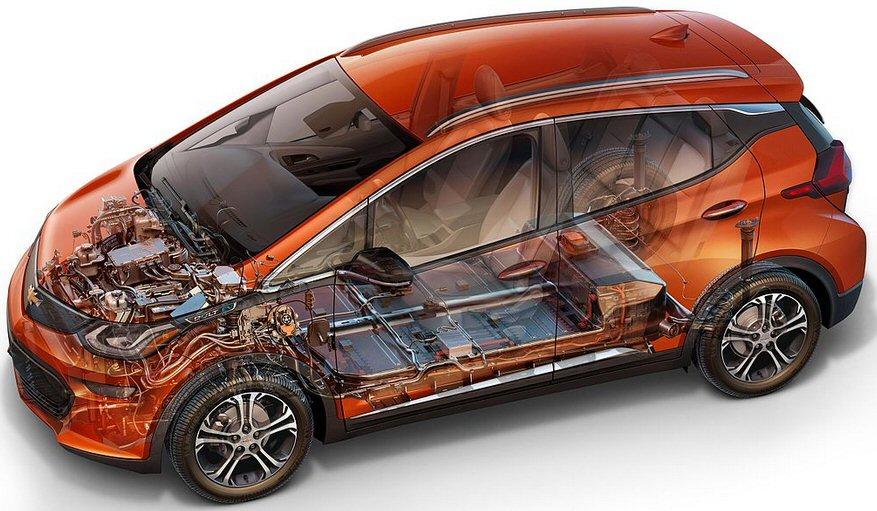
GM's Bolt -- 2nd gen all electric car, 200 mile, for
37.5k
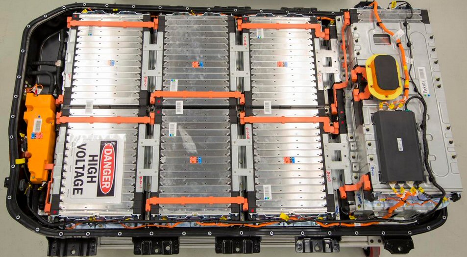
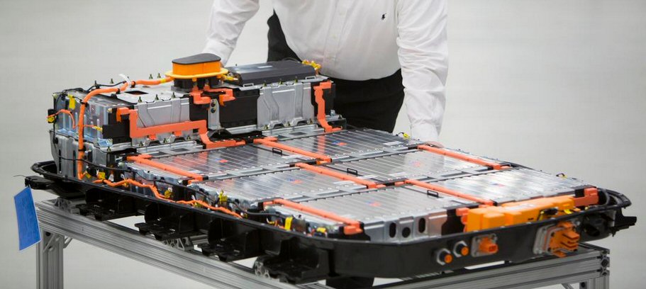
Bolt's 60 kwh flat battery pack with liquid cooling/heating
(april 2016)
..
60 kWh of energy for over 200 miles EPA range
nickel-rich lithium ion chemistry (LG Chem)
battery weight 436 kg (960 lb)
160 kW power output
288 lithium-ion cells (three in parallel x 96 groups in series)
350 V nominal voltage (for 96 cells in series equivalent to 3.65V/cell)
eight years or 100,000 miles battery warranty (GM video says the
Bolt uses the same battery technolgy as the Volt and there are 100,000
Volts on the road and there has been no (loss of) capacity issues with
the Volt battery. Of course, this is somewhat misleading as the Volt battery
gets limited use since this is an extended range EV.)
DC fast charging capability (at least 50 kW we dont know yet for sure
whether GM will enable higher power charging if there will be higher power
chargers) (90 miles/30 minutes)
9.5 hr charging time (from empty) using home 240 VAC charger (25 miles/hour)
Bolt PM motor spec (sept 2016)
GM has pushed
up the max motor rmp to nearly double max rpm of its earlier Spark EV (8,810
rpm vs 4,500). However the Bolt's motor rpm is still much lower than that
the super high motor speeds that Tesla uses (about 15,000 rpm).
150 kW peak power (200 hp)
360 Nm peak torque (266 ft-lb)
8,810 max rpm
7.05:1 gear ratio
total weight of 76 kg
0-60 mph in less than 7 seconds
0-30 mph in 2.9 seconds
Detailed info on Bolt's 60 kwh battery pack
http://insideevs.com/deep-dive-chevrolet-bolt-battery-pack-motor-and-more/
BMW 3 Series
Price
Range
Battery
Wheelbase
Accel (0 to 60 mph)
Availability
-----------------------------------------------------------------------------------------------------------------------
Hybrid
Hybrid cars (like
Prius) are gasoline powered cars that add a relatively small battery and
small to medium size electric motor to assist the engine in driving the
wheels. The key advantage of hybrid cars is that with an electric motor/battery
connected to the wheels regenerative brakes are possible. Regenerative
brakes nearly double city gas mileage, since in city driving much of the
fuel energy is used to repeatedly ramp up the kinetic energy of the car
only to have it all lost (as heat in the brake pads) each time the car
stops. With regenerative brakes much of car's kinetic energy during braking
is captured and saved in the battery. With the electric motor to assist
in acceleration the gasoline engine can be a little smaller and be tuned
for higher efficiency, both of which provide some help for highway mileage.
ElectricsGM Volt
GM advertises the Volt as an extended range electric car, but it is really a quasi-electric/mutant hybrid. It has a moderately sized electric motor and battery, externally charged, and a gasoline engine. In spite of GM's early misrepresentation, the engine is mechanically coupled to the wheels. At first it drives as an almost-electric (assisted by the gasoline engine on hard acceleration). When it runs out of charge, the car runs on the engine (as a hybrid), which since it carries a gas tank, means it's a quasi-electric with no range problem.
a) Pure --- Pure electric car (like Leaf and Tesla) carries a big battery, externally charged, that is the only source of power for the car. This type of alternate car to the usual gasoline powered car has two classic problems (aside from cost): limited range and long fueling time.
b) Extended range --- Extended range electric car (like Fisker Karma, now bankrupt). This type of electric car has both a large electric motor, a modest size battery and a modest size gasoline engine. Unlike a hybrid, the engine is not coupled mechanically to the wheels, it functions as an onboard generator for the battery. The car at first drives on batteries, externally charged, but if the batteries run out of charge the gasoline powered generator cuts in. Since this car carries a tank of gasoline to run the engine driven generator, it solves the range problem.Tesla Model S
Tesla motors (through really good engineering) has had surprising success tackling and (partially) overcoming both of these classic limitations of a pure electric car. They have figured out how to nicely fit a huge battery in their newest model sedan (Model S) and have demonstrated that the battery pack in this car can be rapidly swapped out, thus potentially offering a route to possible rapid refueling.
c) Hydrogen, fuel cell --- A hydrogen fuel cell car (coming in 2015?) is also an electric car, but instead of a (big) battery it has a hydrogen powered electric generator (sort of a flow through battery), called a fuel cell, that runs on a flow of hydrogen from an onboard hydrogen tank. In principle it solves the electric range problem and fueling time problem, but it brings its own (serious) problems. It is expensive to make, puting energy into hydrogen and then taking it out is not efficient, and to be practical nearby hydrogen pumps are required, because home charging with hydrogen is not an option. (I have put material on hydrogen cars in a separate essay.)
Leaf
vs Volt drive train mini-tutorial
(1/29/13) 2012 sales
In 2012 the public had a vote. During the year Volt sales tripled, while
Leaf sales were basically flat (though all sold below original projections).
The public is saying a gas-electric car (like Volt), which has a normal
driving range, is a 'real' car, while an all electric car (even if cheaper
like Leaf), with a very restricted 85 mile range, is not.
-------------------------------------------
(1/5/11)
Here is a technical
comparison of the electric drive trains of the GM Volt and Nissan Leaf,
both of which have just begun deliveries. They are competing cars with
almost the same wheelbase. (Facts about the drive trains are hard to come
by and often come from obscure sources, so numbers are subject to change.)
The Leaf is to the conventional car what the jet is to piston planes. Conventional cars (including the Volt) have a lot of complex up/down stuff (pistons, valves), whereas the Leaf drive train is pure rotary. Leaf is about as simple as an electric car can be: series arrangement of battery, (one) inverter, (one) motor hard coupled to front wheels. Inverter/motors are inherently bidirectional in power flow so the same structure acts as a regenerative brake.
Leaf
battery (90 kw, 345V) ?=> inverter (260A) ?=> PM motor (80 kw) ?=> wheels
(3,366 lb)
The Volt in contrast has a much more complex drive train than the Leaf. Volt's primary drive train has the same components as the Leaf (somewhat beefed up), but it also has a 2nd half sized motor, a 2nd half sized inverter, a complex hybrid type planetary gear set, three (or four) clutches, and a conventional engine! Its battery is 2/3rd the kwh and weight of the Leaf's, but all this extra stuff makes the Volt 424 lbs heavier than the Leaf, and it makes the car more expensive (41k for Volt vs 32.8k for Leaf).
Volt
battery (165 kw, 345V) ?=> inverter (355A)
?=> Induction motor (110 kw) ?=> planetary gears
||
||
?========>
inverter (175A) ?==========>
=> wheels (3,790 lb)
||
||
engine (1.4L, 66 kw) => Induction? mot/gen (54 kw) => planetary gears
Weight ? wheelbase
The hybrid
Prius, all electric Leaf, and electric/hybrid Volt are all build on a 106
in (approx) wheelbase. The Prius is by far the lightest at 3,042 lbs, 324
lb heavier is the Leaf (3,366 lb) and 424 lb heavier than the Leaf is the
Volt (3,790 lbs).
Performance
The Leaf has
a single 80 kw motor/inverter to power the car (under all conditions).
Probably about 40 kw (of its 80 kw) is needed to overcome wind resistance
at 90 mph (top speed) on a flat road.
The Volt has two (and potentially three) sources of torque to accelerate the car: 110 kw main motor, 54 kw mot/gen, and since the engine can be coupled by a clutch to the 54 kw motor, if the gears are rated for it, mechanical torque from the engine could potentially be added too. The result is that even though the Volt is heavier by 424 lbs it accelerates a little quicker (8.8 sec vs 10 sec 0-60 mph for Leaf). Top speed for the Volt is 100 mph vs 90 mph for Leaf.
Confirmation from Volt manual (update 6/12/11)Motor
The Volt manual (p330) says if the car runs out of gas, then the "vehicle will have less responsive acceleration". Looking at the sketch above, the battery should be able to power both motors (110 kw motor and 54 kw mot/gen) to acclerate the car, unless the battery is peak current limited, which is unlikely, so if acceleration suffers when the engine can't run, this is a pretty good indication that the engine is mechanically aiding accleration.
Transmission
The Leaf has
no mechanical or electrical gear ratioing. The motor in the Leaf is hard
coupled via a fixed step down (x7.94) gearing to the wheels. I figure the
PM motor in the Leaf has a speed range of 0 to 9,000 rpm as the car goes
from 0 to 90 mph. The motor Torque vs Speed curve has a power peak probably
near 30 mph (3,000 rpm), and then rolls off in torque faster than constant
hp from 3,000 rpm to 9,000 rpm. This very non-rectangular T vs Speed shape
is needed to get acceptable 0 to 60 mph acceleration times.
Volt with its dual (or triple) torque sources has more options. GM apparently implements a variable speed transmission (like Prius) at higher speeds using gen and/or engine torque to supplement the main motor torque at high speed. This allows them to achieve higher vehicle speeds without excessive rpm on their main motor. They appear to also combine torque sources during hard low speed accelerations. When the battery is depleted, the car runs like a conventional hybrid with peak power from the battery supplementing the 66 kw available from the engine.
Inverters
In both Leaf
and Volt the 345V battery is hard wired to the inverters providing (for
free) a stiff voltage to protect the inverter transistors. Their motors
run at 300 VAC (nom) with currents 250A to 350A, so very likely their main
inverters use 600V IGBTs. In contrast the Prius power path includes step-up
voltage regulator (to compensate for the voltage sag of its small battery),
so it probably runs its motor at 600 VAC (nom) and uses 1,200V IGBTs in
its inverter.
Battery pack
Leaf battery
capacity is 24 kwh (660 lb) of which 19 kwh (80%) is used. Volt battery
back is 2/3rd the size (16 kwh, 436 lb) of 10.5 kwh (65%) is used.
In a striking coincidence? both the Leaf and Volt stack 96 lithium ion prismatic modules in series. While the battery chemistry is a little different, the lithium ion cells in both are 3.6V, so both cars have a battery voltage of 345 VDC (open circuit). The Volt uses three cells in parallel in each module (288 cells total), and the leaf uses two (roughly double size) cells in parallel in each of its modules (192 cells total).
The Volt uses liquid heating/cooling to keep the battery temperature within a narrow range (70F +/- 2F). Volt also uses the engine to protect the battery if the battery gets too hot or too cold. In contrast the leaf just air cools the battery pack with a fan. Its battery temperature varies with ambient, there is even a battery temperature gauge on the dash. And of course they have no engine to protect the battery. It has to power the car even if its cold or hot.
Bottom line is that GM, with its higher battery derating and much better battery temp control, is stressing the battery less than the Leaf, so is likely that its loss of capacity over time will be less than in the Leaf. Leaf (or to be specific its customers!) are taking a chance that there may be a substantial loss of battery capacity in a few years, and surprise (!) Nissan specifically excludes battery capacity loss from the car guarantee. Loss of half the battery capacity in a Leaf would render the car near useless without a very expensive repair, whereas a Volt with a reduced capacity battery will still be drivable.
Hidden advantage of electrics' large battery
Electrics
with their large battery packs have an advantage over hybrids you never
see discussed. This is the issue of battery sag, meaning the sagging of
battery voltage under high demand. In a hybrid the battery accelerates
the car at lower speeds, where the power demands are modest, and is joined
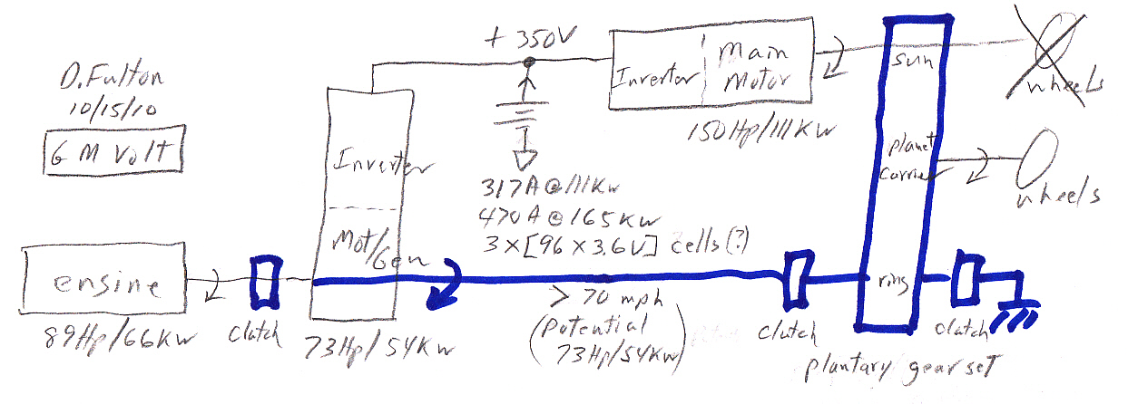
by the engine when power demands increase at higher speeds. My Prius block
diagram (below) shows the Prius battery outputting a peak of 27 kw from
a 1.3 kwh battery. My analysis shows that the Prius NiMH battery voltage
probably sags about 25% under this load. This is a real problem, just when
you need to deliver high voltage to the motor, the battery voltage sags.
To solve this problem Prius from Gen I to Gen II introduced a (bidirectional)
voltage regulator between the battery and inverter. However, this is expensive,
because essentially they had to add a 2nd high power inverter in series
with the main inverter that drives the motor! (It also raised their
bus voltage to about 600V (I think) driving them to 1,200V IGBTs, all of
which needs to be handled carefully from a safety viewpoint.)
A Leaf has
an 80 kw motor, so Leaf's battery needs to supply 80 kw, x3 higher battery
power than in the Prius. But the Leaf's battery is huge compared to the
battery in the Prius (660 lbs, 24 kwh vs 80 lb and 1.3 kwh). While lithium
ion batteries are not quite as good at supplying high current as NiMH used
in hybrids, they are pretty good. Mercedes has gone to lithium ion in their
new hybrid. The peak battery voltage sag in the electrics is probably 10%
or less. This simplifies the electrical design: the battery can be hard
wired to the inverter, no preregulators, no added bus capacitors, and the
stiff battery voltage protects the transistors from overvoltage.
=================================================================
Intro
A primer on
the electrical power designs of hybrid cars and electrics by a (former)
inverter designer including my Toyota/Ford/Lexus block diagram with gen
III Toyota Prius values (below) and a circuit sketch of Prius voltages
and currents. I'm not a guy car. I have little real understanding of mechanical
components like gears and transmissions, but I do understand the basics
of the (famous) Prius 'power splitter'. I don't own a hybrid, so I can
contribute nothing from a user viewpoint, but I do know electronics.
So what is a hybrid car?
Hybrid cars can be viewed as gasoline based cars that obtain superior efficiency by employing a very sophisticated electrical/mechanical transmission. The transmission is coupled to a small rechargeable battery sized to to smooth out the peak power demands of driving, allowing the engine to be downsized. Additional efficiency improvements in city driving are obtained by employing regenerative braking that recovers the car's kinetic energy when stopping and wasting of fuel when the car is stopped in traffic is prevented by turning off the engine.Toyota/Ford/Honda/Lexus hybrid block diagram
The hallmark of this hybrid architecture is a CVT (continuously variable transmission) implemented by a planetary gear set (power splitter) that splits off part of the engine power to a generator. The control of the power split is achieved by the control of current in the two inverters that drive the two electrical machines. There are no clutches or (mechanical) transmission.
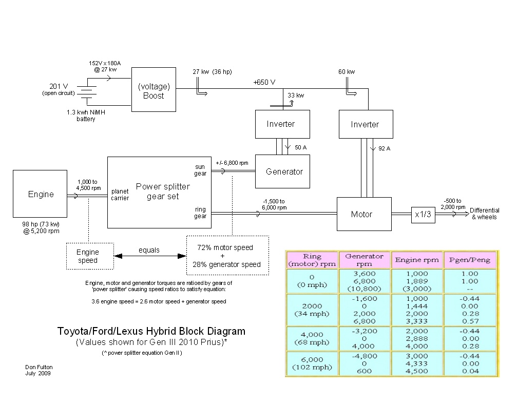
my original figure (all rights reserved)
How to think about the architecture
In a hybrid
car the small battery can only provide bursts of power. Most of the time
when driving in a hybrid there is no power flow in or out of the
battery, all the energy needed to drive the car comes from the engine,
but in the architecture above there is two paths for the engine power to
get to the wheels. In the lower path the engine power (from the ring gear)
passes mechanically through the motor. In the upper path the engine power
(split off via the sun gear) is converted by the generator and its inverter
to DC power and reconverted from DC to AC power (and torque) by the motor
and its inverter.
Consider first
the case where the generator speed is held zero, note this requires
the generator to be current driven so it can 'push'. In this case there
is no power flow out of the sun gear, all the engine power flows
via the lower path out of the ring gear to the wheels. The planetary gear
set in this circumstance provides a fixed ratio between engine and
output shaft, which as the numbers in the figure show is small speed step
down with corresponding torque increase [output torque = x1.39 engine
torque].
CVT (continuously variable transmission)
Consider a
given wheel speed. The planetary gear set equation (see figure) shows that
if the generator is allowed to spin while the wheel speed is constant the
engine speed must change. In other words the equation is saying the engine
speed can be driven (smoothly) up and down by rotating the generator at
various speeds either CW or CCW. Of course, since in normal driving the
engine is still providing all the power to the wheels, as the speed
of the engine is forced down, say for cruising on the highway, the torque
load on the engine must increase. Thus this architecture does indeed provide
a 'continuously variable transmission' with the ratio of engine speed to
wheels speed controlled by the generator speed (and direction).
Since power is torque x speed, when the generator is allowed to rotate it means some of the engine power flows though the upper path. Surprisingly in one generator rotation direction the power flow in the upper path is not left to right, but right to left. What happens in this case is that 'excess' power flows out of the ring gear, is bled off by the motor and fed back around into the sun gear via the generator.
How to think about the power splitter
In a planetary
gear set the ratio of torques among the three shafts is fixed by
design [number of teeth and gear dia]. In a well designed gear set [power
in = power out]. For each shaft [power = torque x speed], so writing the
power equation and substituting the fixed torque ratios results in a planetary
gear set also having a fixed speed relation among its three shafts
(as shown in the figure).
VW
introduces a very different hybrid architecture (4/13)
VW new to
hybrids in 2013 has gone a different way. They are not using the nearly
universal Toyota power splitter architecture, instead they have brought
to market (VW Jetta 2013 hybrid) what is to me a totally new architecture.
Since this block diagram is very simple and clean, I am sure it has long
been known, but as far as I know this is the first time anyone has done
the engineering and brought it to market.
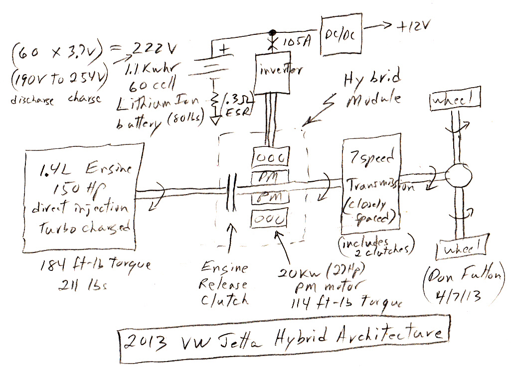
I derived this sketch from a long tutorial by VW engineers
This hybrid architecture is radically different from the Toyota architecture, both in design and performance. For one thing the three shaft 'power splitter' is gone. Here torque (and power) are combined simply by wrapping the motor around the engine output shaft. And this hybrid has a real (mechanical) transmission, a 7 gear transmission (used in other VWs), so as the car accelerates it can be felt going through the gears. A high power, electrically controlled, 'engine release' clutch whose job is to switch the engine in/out is integrated with the motor. This combo VW calls the 'hybrid module'.
Electrically it is simpler than the Toyota style hybrid because it has only one motor/inverter rather than two. The mechanical complexity of the Toyota planetary ring gear assembly is replaced by a [standard transmission + (engine release) clutch]. The single motor is also the starting motor for the engine, which always turns off when it is disconnected. There is no +12V battery in the car, a DC/DC converter steps down the 222 lithium ion battery pack to 12V to drive all the accessories.
The VW Jetta hybrid is a little (7") longer and an inch wider than the Prius though it's built on a slightly smaller wheelbase (104" vs 106"). The Jetta weighs about 10% more than than the Prius (3,312 lb vs 3,042 lb). The VW electrical motor is a little smaller than the Prius (20 kw vs 27 kw) but the VW turbo charged engine has a lot more power (150 hp vs 98 hp), so the VW Jetta total has about 30% higher peak power than the Prius. The difference in torque is even more striking with the Jetta speced at 184 ft-lb and the Prius at only 105 fl-lb. Both have the same EPA highway rating (48 mpg), but the Prius EPA city is rated 51 mpg vs 42 mpg for Jetta. The lower Jetta City rating may reflect losses in the transmission, which is in the brake/regen path.
Battery and modes
Like other newer
hybrids VW has gone over to a lithium ion for the battery. VW describes
the battery pack as 20 kw discharge and 28 kw charge. Assuming this is
all due to the ESR, I can calculate that the battery is pretty stiff with
about a 15% sag at max 20 kw load and a 15% rise at the same charge current.
The engine release clutch provides this architecture with four operating
modes:
Start/low speed and regen braking
pure electric, clutch open (engine off)
Highway driving
clutch closed, no motor current (car runs only on 1.4L engine)
Power boost, full acceleration
clutch closed, both engine and motor provide torque
Performance
The 4/13 NYT review
describes this car as "a mix of efficiency, precise handling and high-speed
confidence not previously offered in a hybrid." Other reviews show 8.5
sec to 60 mph, but gas mileage is not as good as pokier hybrids. The gear
shifting can clearly be felt, and the transitions from mode to mode were
described as being not as smooth as in Ford and other hybrids. Whether
this is because VW is new to hybrids or is inherent in the architecture
is an interesting question. (Other reviewers, however, say the engine on/off
transistions are smoother, and you need to look at the display to
tell if the engine is running.)
Summary overview -- (or what I learned researching
? writing this essay)
There are
key choices to be made in building a hybrid or (quasi) electric car, and
one of my goals in researching this essay was to understand how ? why the
particular choices have been made. Battery type and hybrid architecture
have been discussed ad nauseaum, but there are many other key choices:
Motor (? generator)
type
PM (+ reluctance) or induction
top speed
6-7 thousand or 12-14 thousand rpm
cooling
air or water
Inverter
transistor/IGBT
600V or 1,200V
bus voltage
fixed or varied
paralleled
no or yes (if yes, how paralleled)
cooling
air or water
Battery voltage
booster yes/no
Battery
type
NiMH or lithium ion
voltage sag
low (15 to 20%), moderate (25%), heavy (50%)
oversizing
oversize vs lifetime trade
forced air cooling
yes/no
ESR at low temp
how to live with a x3 to x6 increase in ESR
Engine
speed range
fixed or variable
peak hp operation
yes/no
Motor
All the hybrids
are using (neodymium) PM motors, but the two (quasi) electrics are using
induction. My guess is PM motor/generators being smaller integrate best
with sun/planet power splitter used in the Toyota/Ford/Lexus hybrids. Induction
motors are favored with the motor needs to be larger, need to run hotter,
and can stand alone.
Motors are sized by torque, but power is T x speed, so doubling a motor's speed (6,500 => 13,000 rpm) can roughly double its output power. Toyota uses this technique for its 133kw hybrid SUV (Highlander), combining it with a 2:1 step down to allow it to mate with the 6,500 rpm power splitter gears. Tesla Motors uses it too, operating the motor to 13,000 rpm. For PM motors to work well in vehicles a special control technique is needed to add a (nominal) constant hp region to T vs S. This either means field weakening, or a combo PM/reluctance motor as Toyota is using. There is little info available as to the technology used for generators, but it's a good guess that if the motor is PM, then the generator is too. Didn't find much about how motors are cooled.
Inverter, voltage sag, and battery (voltage) booster
There are
two standard types of IGBT (transistors): 600V and 1,200V. Battery
pack voltages in current vehicles range from 160V to 320V, so if battery
pack couples directly to the inverter, then 600V IGBT's are used. This
was the technique used in the gen I Priuses, and it is the technique used
in the Tesla Motor's Roadster electric car. However, at this low voltage
when a lot of inverter power is needed, like in an electric car, the currents
get 'wicked' high. Tesla's inverter is rated for 850A and achieves this
with massive paralleling (x11).
A problem with direct battery to inverter connection is that the battery voltage sags a lot when it must deliver peak power/current. If you try to pull the absolute max power (100%) the battery pack can deliver, its terminal voltage will sag 50%, meaning the terminal voltage drops in half. This is undesirable for a lot of reasons, so a compromise is called for. I calculate that Toyota limits battery voltage sag to 25%, at which point the battery delivers 75% of its maximum power. In this configuration battery voltage sag rounds off the corner of T vs Speed, reducing the peak output power.
Adding a voltage booster, which is a specialized inverter, between the battery and inverter does a couple of things. First, it improves peak output power because the inverter/motor no longer 'sees' the battery voltage sag. Second, by roughly doubling the voltage to the inverter it halfs the current (for the same power) in the inverter and motor. The higher voltage is handled by using 1,200V IGBT's. Toyota added a booster in 2003 in the transition from gen I to gen II. A draw back is that the booster needs to handle the full power of the battery pack and has to handle bidirectional power flow to allow regenerative braking. A still further complication is that all converters need a large inductance to 'switch against'. In the motor and generator the needed inductance is free, it's built into the motor and generator, but with the voltage booster it must be added in. I have seen zero info about the voltage booster implementation. A further, non trivial, complication with adding a booster is that a (bigger) bus capacitor bank is needed to handle the switching currents from the inverter, because the stabilizing influence of the battery low impedance is no longer visible through the booster.
Toyota appears to regulate (fix) the bus voltage of their inverters using the booster at 650VDC, but some optimization is possible by allowing the bus voltage to vary with vehicle speed and conditions. Ford appears to be modulating the bus voltage up and down a little in the 2010 Fusion. Tesla Motors (might) be doing this too with a cryptic reference that they were (somehow) dropping the bus voltage when the inverter needed to output its maximum 850A during low speed acceleration. The only company that appears to be paralleling is Tesla Motors, apparently they use 66 IGBT's whereas nominally for a motor inverter only 6 are needed, implying they are paralleling x11 to reach 850A. Paralleling is non-standard and can probably be reliable, but it takes careful engineering. Power semiconductor companies are beginning to make high current modules with paralleled die specifically for (electric) vehicles (see below).
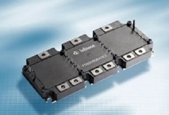
800A (550A with 75C water cooling), 600V six-pack
inverter
(probably 2 x 400A parallel IGBT die in all six locations)
size: 8.5" x 4", dissipation: 1,500W (max)
Important: mating (six terminal) snubbing capacitor
available
Infineon
FS800R07A2E3
Three inverters in a hybrid --- Look at my Prius block diagram, there really three inverters. In addition to the full power (60kw) motor inverter there is the half power generator inverter (33kw) and the half power voltage booster inverter (27kw).
I found little (hard) info available on inverter cooling, but a poster says Prius uses liquid cooling for the inverter and motor (separate cooling loop from the engine) and air cooling for battery pack. (Prius inverter enclose does appear to show liquid ports.) A new Tesla owner reports he took his 100k new Roadster to an off road amateur (twisty) track and found his inverter over-temperature warning light came on in five minutes followed by the over-temperature warning light on the motor. (It's high performance car, but only for 5 min!) Researching I found out the idiots at Tesla Motors air cooled the inverter. I've worked with both water and air cooling on high power inverters and water cooling is (at least) x5 more effective than forced air. All high power inverters and (PM) motors in vehicles should be water cooled.
Toyota's Atkinson cycle engine
A 2007 UC
Davis paper (see reference below) discusses the 1.4 L (gasoline) engine
used in the Prius. It says it is the most efficient gasoline engine in
production (as of 2007). It uses the Atkinson cycle as opposed to
the Otto cycle used by most (or all) car engines. Here's the comparison
they make:
Atkinson
Otto
-------------
------
Peak thermal
efficiency
37%
25%
Power/Torque
output
(Atkinson 20-30% less than Otto of same size)
According to this paper the Atkinson cycle has a huge effect on performance. In exchanged for a 20-30% loss in power and torque almost a 50% improvement in fuel efficiency is realized! (Is this reflected in Toyota gas milage numbers?) It is consistent with Ford Fusion, which has very good gas milage numbers. Ford Fusion too uses an Atkinson cycle engine, and it's quite large 2.5L (vs 1.8L is gen III Prius).
Batteries
All hybrids
on the market use relatively small NiMH battery packs (100 lbs or so).
It turns out that remarkable little energy storage is needed to get big
improvements in mileage, especially city mileage. Ford touts their new
2010 hybrid can go 47 mph on battery, but the driving range in all electric
mode is only a couple of miles. Batteries at full power discharge in 30
sec or so. The improved gas mileage, which can be double for city driving,
is achieved by downsizing and optimizing the engine cycle and speed and
capturing a significant fraction of vehicle kinetic energy with regenerative
braking.
Available data indicates that NiMH battery lifetime in hybrids has proven to be remarkably good. This indicates that oversizing the battery and small discharge cycles in hybrids (engines quickly recharge the battery after an acceleration) have been very effective at extending battery lifetime. This problem is much more difficult in electric cars where deep discharge of the batteries is required for long range. To improve range higher power density lithium ion batteries will be used, and battery packs will be x4 heavier (400 lbs or so) with x12 energy storage (16 kwh vs 1.3 kwh). (Of course, the battery people are working discharge cycle problem hard and 123 Systems, for example, touts the x10 higher discharge cycles that their battery technology can deliver as a major advance.)
Batteries at peak power can dissipate a lot of power and their chemistries don't like high temperature, so battery cooling is required. If the battery pack is pushed to its limit to deliver peak power ('matched load'), it will dissipated an amount of heat equal to what it delivers. Toyota (I figured out) compromises by restricting the peak load to 75% of battery maximum. This reduces battery heating to 1/3rd of delivered power, which is much better, but it's still a lot of heat. As far as I can tell, everyone air cools their battery pack. A photo of a Toyota SUV battery pack shows three high power axial cooling fans. But I read the GM Volt, who have a much more difficult battery thermal problem with their large lithium ion battery pack, may be using liquid for its temperature control.
NiMH battery data sheet from Panasonic shows a big loss of peak power capability in cold weather (reduces by x3 to x6). Apparently in hybrids this is little noticed, probably because the engine is cut in much sooner. However, it led Audi to cancel a high performance hybrid SUV they were developing when they found the snappy acceleration was just not there in cold weather.
Low temperature data ? peak current discharge on lithium ion batteries for vehicles are (suspiciously) not available. Not only has GM not released its battery spec, but the LG Chem has pulled all the detailed specifications for its (custom) lithium ion batteries. Likewise 123 Systems have not disclosed their vehicle battery spec.
Engine
Marketing
literature sometimes gives the impression that the engine in a hybrid or
an extended range electric need only run at one speed (or a very narrow
speed range). This is partially true, but is somewhat of an exaggeration.
The Prius engine runs from 1,000 rpm to 4,500 rpm (5,200 rpm in gen III).
The lossey high end range of 4,500 to 6,500 rpm of the conventional engine
is gone. While the GM Volt literature claims their engine mearly recharges
the battery, it appears that they sometimes need to run the engine at its
maximum power point (its highest loss point) so that raw generator current
can supplement battery current (increasing it 33% or so) to increase the
driving hp, or on long trips or cold temperatures power the vehicle fully.
Introduction
Here is a
primer on the battery/inverter technology in hybrid cars from a power/motor
control engineer. In the early hybrid years of Toyota ? Honda technical
details were hard to come by, even to someone working in the power engineering
field. But now a decade later some information about the technology has
been published, and with hybrid cars slowing going mainstream and performance
improving I decided it was time to take a look at the electrical engineering
of hybrid cars. The new 2010 Ford Fusion, which is getting great reviews,
is pushing the all electric envelope, touted as able to run all electric
up to 40+ mph. It seems hybrid cars are slowing getting more and more electric,
in a sense they are evolving toward all electric cars.
I know a lot about inverters, because I used to design them. I've designed little ones and big ones, some as big as those in current hybrids and some bigger. I know a lot about motors too with patents on the control of PM motors and induction motors. I know relatively little about batteries, but I know how to read a data sheet and can often take a few pieces of published data and made reasonable guesses to fill in the gaps. Toyota, of course, was a pioneer in hybrids and has been selling them for more than a decade. They just now introducing their third generation of hybrid technology.
I focused on the major hybrid manufacturer, Toyota, and quickly found the spec of the Panasonic battery used in the Prius. A colleague provided me with a recent paper by a Toyota engineer that describes the development of a higher power (123 kw) inverter and motor for use in a 2005 Toyota SUV. A link in Wikipedia led me to a detailed description of the Prius power splitter by a Prious owner and engineer. I started this essay to record what I recently learned about hybrids, and as a place to put new hybrid info as it becomes available.
I've gained a good understanding of the Prius/Ford/Lexus architecture. By feeding the engine power to the wheels through two parallel paths: mechanical (sun/planetary gear set) and electrical (two motor/generators + inverters coupled together), two birds are killed with one stone: It works as a continuously variable transmission, and it provides a DC node where the battery (or boosted battery) can be connected. Since every element in the structure (inverters, motor/generators, booster, battery, even the engine) allows bidirectional power flow, the system is very flexible and can be operated in five or six modes. To an engineer it's very sweet.Batteries
Hybrid vs electrics
The batteries
in hybrids (like Prius) and electrics are very different. In a hybrid the
battery pack is tiny, only a 70 to 100 lbs. It's used for a few seconds
to boost acceleration and for low speed driving where power load is low.
The engine quickly recharges the battery so the usual discharge is shallow.
Batteries like this.
In contrast trying to drive on the highway any significant distance using only electric power is a bitch. The Tesla Roadster battery pack has x43 more energy storage than Prius (56 kwh vs 1.3 kwh), it weighs 1,000 lbs, costs a ton, and still only give 220 mile range in a two seater car.
With current battery technology the electric guys face a nasty trade off: battery life vs depth of discharge. Rechargable power tools fully discharge their lithium ion batteries with the result that the batteries are seriously degraded in three years. GM must be sweating this problem with the Volt. Their current compromise is to 50% discharge the battery. If they 100% discharged, they would double range from 40 miles to 80 miles, but then their batteries would begin to die in three years. The battery manuf are working this problem hard using a fundamentally new class of materials with very high surface area (nano technology) and are claiming x10 improvements in battery life.
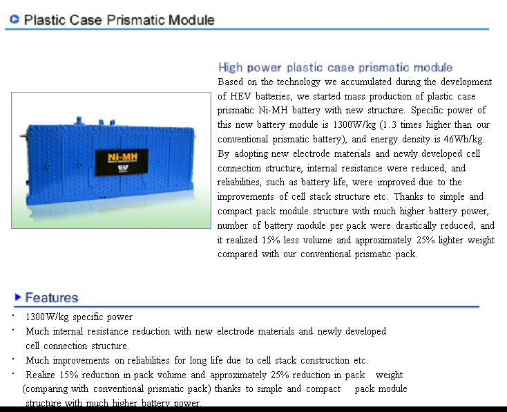
Nickel
Metal Hydride (NiMH) batteries
Currently
(as of summer 2009) all hybrid cars on the market use Nickel Metal
Hydride (NiMH) batteries. Typically they use a single stack of 170 to 260
cells in series (D type or equivalent @ 1.2 V/cell), which results in an
'open circuit' voltage in the 200V to 300V range. Amazingly these cells
can (each) handle hundreds of amps for a brief time (seconds).
High peak power
In addition
to good energy storage, a critical requirement for a vehicle battery pack
it must have very low internal resistance so it can deliver large
amounts of current and energy quickly to accelerate the vehicle. Low battery
internal resistance is also needed to efficiently absorb the regenerated
braking energy, which tends arrive in the form of high power/current pulses.
It is the capture of the vehicle's kinetic energy via regenerative brakes
in a hybrid that makes a hybrid's city mpg higher than highway mpg, exactly
the opposite of conventional cars.
Prius NiMH numbers
The internal
resistance of the 1.2V Panasonic cell (see below) that Panasonic says is
used in the Prius ? some Lexus hybrids is only 1.66 mohm. This gives a
short circuit current in the range of 720A = 1.2V/(1.66 x 10^-3 ohm)!!
The battery manufacturer rates the 'output power' at its max (of course).
A little back of the envelope scribbling shows the battery manufacturer
(peak) 'output power' rating is for a matched load, meaning a load resistor
equal to the internal resistance of the battery. For the Panasonic Prius
battery peak power out is 360 A out (half short circuit current) at half
voltage. In round numbers the maximum power that a 200V battery pack can
deliver is 100V x 360A = 36kw (48 hp). This number is in the ballpark for
electrical hp for current car hybrids (electrical hp numbers are substantially
higher in SUVs and trucks), so it is likely that hybrid cars manufacturers
do in fact push their batteries pretty hard, either up to or near their
rated peak power point.
Realistically NiMH batteries can only deliver high peak power for a few seconds at a time, because at maximum discharge rates a fully charged battery pack is fully discharged in about one minute. Wikipedia says early model Priuses would fully discharge the battery traveling 2,000 feet at 90 mph up a 6 degree slope. This works out to battery discharge in 15 seconds, since at 90 mph the car is traveling 132 ft/sec. (I later found out the explanation for the difference between 1 min and 15 seconds. Toyota restricts the charge/discharge range of the battery pack for battery lifetime reasons, keeping it between 40% (or 60% references differ) to 80% of capacity.)
You can only run most hybrids in all electric mode to about 25 mph. You can't run the useless GM car 'mild' hybrids in all electric mode at all. Customers soon figured out this was pretty useless and didn't buy them, so recently (June 2009) GM announced they are going to stop production of all their hybrid cars (they will still have some hybrid trucks)! The new 2010 Ford Fusion hybrid, which is getting raves, can reportedly go 40+ mph in all electric mode.
Load conditionsVoltage sag
A simple, useful model of a battery cell is a voltage source (ideal battery) in series with a resistor, typically called the 'ESR' or 'Equivalent Series Resistance'. The ESR in the model causes the battery terminal voltage to sag when current is delivered to the load, just like in a real battery. Electrical engineers routinely characterize systems like this under two load conditions: 'no load' and 'short circuit'. At 'no load' the voltage (V) is measured with no current drawn from the battery. 'Short circuit' is a measurement of current (Iss) that flows (through the short) when the battery terminals are shorted, it is the no load voltage divided by ESR (Iss = V/ESR). In both of these cases the useful output power, meaning power to the load, is zero. Why? Because P = V x I, and in the former case I is zero, and in the latter V is zero.Matched load
If you do the math, you find the maximum power the battery can deliver occurs when the voltage and current are half way to their maximums. This occurs when the battery 'sees' a load that has a resistance equal to its ESR, this is called a 'matched' load. Under these conditions the battery terminal voltage sags to half the open circuit voltage (Voc/2), because the intrinsic cell voltage divides equally between the two ESR's, one inside and one outside the battery. The current that flows is half the short circuit current because the total resistance 'seen' by the battery is doubled (I = Voc/(2 ESR) = 0.5 Iss). The formula for maximum power out is:Pmax = 0.5 Voc x 0.5 Iss = 0.25 Voc x Iss
where
Pmax = peak power out (watt)
Voc = open circuit voltage (volt)
Iss = short circuit current (amp)
Heat dissipation
Another complication
is that when the battery pack is delivering high power it is also dissipating
high power. If the Prius battery pack was allowed to deliver its maximum
36kw to the motor, it would be at the same time dissipating an equal amount
of power (36kw) internally. In other words at maximum power out half of
the cell's stored energy is being lost as heat dissipation within the cell.
36kw is a lot of power, but [energy = power x time], so the energy to be
handled thermally is bounded and calculable. Initially the heat energy
is absorbed by the thermal mass of the cell chemistry, and over longer
times the battery pack must be able to dissipate the average heat lost
in the cells. (I have yet to find any info on temperature rises or battery
cooling)
After writing above, I found from working the gen III numbers that Prius limits the peak power flow from the battery pack to 75% of its maximum power out capacity (matched load) as rated by the battery manufacturer. This modest (25%) reduction in peak battery output power makes a huge reduction (factor of 4) in the heat energy lost in the battery during peak loads.
Lifetime/charge cycles
Wear out of
rechargeable batteries is strongly depended on the size of their charge/discharge
cycle. Batteries in portable equipment, which are deeply discharged, have
only about a three year lifetime. NASA uses batteries in satellites with
solar panels to ride through the satellite night and gets good lifetime
by oversizing the batteries so they only discharge about 10%. This is the
trick used in hybrid cars. Even though the capacity range is limited to
something like 25% (20% to 40%) in most driving the discharges from acceleration
are no more than 10% with a quick recharge from the engine. This is how
the battery lifetime in hybrids is extended to give an eight years guaranteed
lifetime.
But this trick doesn't work (or work well) when the goal is to drive long distances on the battery, like the GM Volt or the Tesla Motors all electric car. GM is stricking a compromise by restricting the usable range of its lithium ion battery to 50% (30% to 80%). An effort to extend battery lifetime probably also explains the unusual cycle they plan to use. When the battery discharges to 30%, the engine turns on but it does not charge the battery. It just provides the average power the car needs while holding the battery charge (nominally) at 30%. Only when the car is plugged in is the battery charged back up to the 80% level. This prevents multiple battery cycles that would otherwise occur on long trips.
Another issue with battery capacity is that charging losses rise (substantially) as the battery approaches its capacity limit, meaning ESR starts to rise as capacity exceeds 80%. For this reason the top 20% of battery capacity is not very useful.
Info in this section is from a guy who makes battery testing equipment and who writes lots of battery articles. His site has a good article on how the lithium battery (with lithium metal) was unstable and dangerous and how it evolved into the lithium ion battery to solve this problem. He also has info on pros/cons of various lithium ion chemistries.
123 Systems lithium ion cells 'claim to fame' is that their cells with nano technology have nearly solved (or greatly improved) the degradation with load cycle problem. They have data on their site showing cells still good after 300,000 cycles. They argue much less 'over capacity' need be designed into the battery pack with their cells to get the desired lifetime. (Not particularly useful to a vehicle manuf if he wants a 2nd battery source!)
Prius NiMH battery
I was able
to get a good handle on the Prius battery pack by finding a data sheet
from Panasonic, who makes the NiMH battery cells used in the Prius battery
pack. Here's the link:
http://www.peve.jp/e/hevjyusi.html
The curve below shows the internal resistance (ESR) for a module (6 cells in series) is about 10 mohm. This makes the short circuit current an amazing 7.2V/0.01 ohm = 720 amp! This is confirmed by Panasonic's (peak rated) 'output power' of the module at 1,350 watts. The simple voltage source/ESR battery model predicts peak output power at half open circuit voltage (3.6V) and half short circuit (360A) current, and 3.6V x 360A = 1,296 watts (within 4% of the 1,350 watts on the data sheet).
Battery type
D ?? (or DD??) NiMH (Nickel metal hydride)
(nope, the module is too narrow for D cells)
Prius ? Lexus battery Panasonic
Prismatic Module
6 cells series (7.2V = 1.2V x 6)
10 mohm (for whole 6 cell stack)
6.5Ah (for cell and whole battery pack)
28 modules x 6 cells/module = 168 cells
battery pack weight = 28 modules x
1.04 kg/module x 2.2 lb/kg = 64 lb
(additional weight for structure)
open circuit voltage = 168 x 1.2V/cell = 201 V
Kwh for Prius 201V battery pack
201V x 6.5Ah =1.3 Kwh (OK, agrees with published)
7.2V/.01 ohm = 720 A short circuit (calculated)
Max power out (theoretically) with matched 0.01 ohm load
Pout = 3.6 V x ( 7.2V/ .02 ohm)
= 3.6V x 360A
= 1,296 watts (for a module of 6 cells in series)
Rated Power out = 1,350 watts (OK, this is obviously max
with matched load)
The two figures below are the Panasonic data sheet from which I extracted the info above. Note the module contains six cells 1.2 V cells (all NiMH cells are 1.2V) in series giving it an open circuit voltage of 7.2V. At rated peak power out half the 7.2V of the cells drops across the internal ESR (equivalent series resistance) and half across the load. This means the voltage seen by the load at peak power out is 3.6 V (half of 7.2V). So at 1,300 watts out, the current out, and in each cell, must be 1,350W/3.6V = 375 A.
I had read that D cells were the used in the Prius, but that can't be right, because the dimensions of the module are not consistent with D cells, it's too thin. D cells are 1.3 in in dia, but the thickness of this module is only 0.77 inches. Its dimensions are 0.77 in x 4.2 in x 11.2 in and it weighs about 1 kg. (Here's the story from Wikipedia: The original Prius used shrink-wrapped 1.2 volt D cells, and all subsequent THS/HSD vehicles have used custom 7.2 V battery modules mounted in a carrier.)
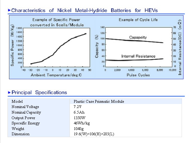
Panasonic Prius NiMH battery module data sheet
Weight
I was surprised
to find how light the Prius battery pack is, it's only 80 lbs (other references
say 100 lbs and Wikipedia says 118 lbs). Each of 28 modules weighs about
a kg which totals to about 64 lbs. People who make advanced battery packs
for the Prius give the weight of the standard Prius NiMH battery pack as
80 lbs, which is confirming, 64 lbs of cells + 16 lbs of structure.
Discharge time
At peak power
out each NiMH cell is dissipating 216 watts = 0.6V x 360A!! At full current
(360A) the battery cell run down time is only 6.5Ah/360A x 60 min/hr =
1.08 min.
Here's the discharge calculation from a power point of view. The Prius battery pack has 168 cells in 28 modules, which at 1.2V/cell gives an open circuit voltage of 201V. Each cell has a current rating of 6.5 Ah, which at 1.2V/cell is a watt storage rating of 6.5 Ah x 1.2V = 7.8 watt-hour. The 168 cell battery pack thus has energy storage of 168 x 7.8 watt-hour = 1.31 kwh, which agrees with what I see quoted for the Prius battery. At the maximum discharge rate 36kw is delivered to the load and 36 kw dissipated as heat in the cells, so the discharge time of a fully charged battery pack is in the range of 1.31 kwh/(72 kw) x 60 min/hr = 1.08 min.Repeat, a fully charged Prius 1.3 Kwh battery pack can only put out 36 kw (48 hp) for about 1 min before it is fully discharged! The fact that such a battery can effectively assist the car with power in/out peaks, shows that in real world driving power peaks must be relatively brief and separated in time. (Actually the Prius battery maximum load discharge time is probably closer to 30 sec than 1 min. Prius limits the peak discharge rate to 27 kw, which doubles potential discharge time, but for battery lifetime reasons only a small fraction of the battery capacity is used.)
Discharge limits
I read that
Toyota limits severely the usable kwh range of the NiMH battery pack, and
this is done to extend the battery pack life (guaranteed for 8 years).
One reference said the charge of the batter pack is held within 40% to
80%, Wikipedia says 60% to 80%. The first limit would restrict the usable
kwh range to 40% of the nominal 1.3 kwr energy storage and 2nd limit is
only half of this or 20% of the nominal energy limit! Note these are are
not
peak power limits, these are energy limits. The charge of the battery pack
must always be held somewhat below 100% to provide a reserve for regenerative
braking.
There may be peak power/current limits too, but I have not seen a definitive reference. One reference said the battery current was limited to 80 A, but this seems far too low, compared to the 360A that I calculate the batteries could deliver with a matched load. An 80A limit in the new Priuses with only 28 modules would limit the peak battery power to 14kw = 80A x [201V (open circuit) - 80A x 28 x 0.01 ohm] = 80A x 179V = 14.3 kw (19 hp) (After I wrote above, I figured out that the Toyota limits peak battery power to 75% of maxium (see below), which results in maxiumum battery current of 180 A in gen III Prius.)
Low temperature problem?
Notice the
left curve in Panasonic data sheet. It shows a shows a horrendous drop
off in peak power with temperature. At -10C (14F) the peak power is down
by something like 2/3rd (400 kw/1,300 kw = 0.31). At -25C (-12F) it's halved
again! Since the open circuit voltage is fairly temperature insensitive
(maybe -10%), the power roll off means the ESR of the cell roughly triples
at low temperature (and 14F is not that low). My guess is that this is
not too serious a problem for current hybrids, because the control system
can compensate by cutting in the engine at lower speeds in cold temperatures.
(should see if I can find reference to this in literature).
But in a car like the GM Volt, where I estimate that 3/4 of the peak power comes from the battery pack a big increase in ESR at low temperatures in its lithium cells would substantially reduce the effective 'hp' rating of the car until the batteries warm up (if they ever do). I have been unable to find data on ESR vs temperature for various lithium ion cells.
(update)
I searched
for people complaining about poor acceleration in cold weather and found
little. Maybe the explanation is this:
"When you start the Prius with a cold engine, its top priority is to warm up the engine and catalytic converter to get the emission control systems going. The engine will run for several minutes until this happens (how long depends on the actual engine and converter temperature).If the engine is routinely started in cold weather, then the inability of the cold NiMH battery to deliver high current is masked. People on forums did complain of poorer mileage in cold weather, but there are lots of reasons mileage falls off in cold weather.Unfortunately, it is not possible to prevent the ICE (engine) from starting when you turn on the car, even if all you want to do is move the car onto the driveway to wash it."
(update) I was right to be concerned about the large increase in ESR at low temperataures. A 2008 story say Audi cancelled a planned (high performance) hybrid saying (essentially) that the NiMH batteries stink at cold temperatures:
"Audi explained that they were not satisfied with the poor cold weather performance and limited capacity of NiMH batteries. When the batteries are low, the vehicle loses a significant amount of performance and Audi engineers wanted to ensure that the performance was consistent. They don't want a driver to pull out for a passing maneuver and have less acceleration than expected due to a cold or flat battery. VW and Porsche are proceeding with their nickel metal hydride battery hybrid plans."(update 10/2/2011)
"At 32? F (0? C), range is cut in half; above 77? F (25? C), when the air conditioning kicks in, the range sinks again. But in addition to the effects of weather on the draw of electricity, Toyota also found a traffic jam effect. In good weather on the same route, when the drives averaged 19.4 mph, the EV range was about 4 miles more than when speeds were averaging 13.7 mph." (4 miles/13 miles 'traffic jam' is a 30% effect. No explanation as to why, but my guess is much of the low speed stop/start kinetic energy is not captured by the regerative braking.)At 32F the Toyota lithium ion battery has lost half its capacity! I bet it loses another half at 0F.
Tesla
battery low temperature problem (2/10/13)
[90 miles => 25 miles] explained? (2/14/13 update)
NYT auto reviewer
(John Broder) just wrote a follow up piece discussing his (infamous) Tesla
Model S test drive, and one of the mysteries is partially explained. A
Tesla rep told him much of the car's range loss overnight [90 miles =>
25 miles] was due to a "software glitch". Translation: With the car parked
overnight at the hotel (not plugged in) something inside probably came
on and drained the battery. I'll make a guess that the battery heater was
pulsing ON trying to keep the battery temp from dropping to 10F, the outside
temp in the morning.
But the story gets curiouser....
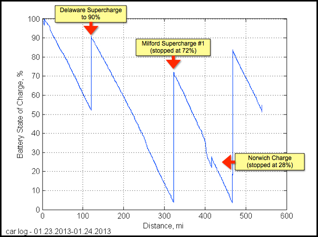
Musk publishes on the Tesla web site a detailed rebuttal to the NYT story (above) and includes the data logs of the test car, which does indeed show a step drop in range (85 => 20 miles), but curiously a lot smaller drop at the same time in capacity (38% to 30%, or 6.8 kwh lost), so the rest of the range lost must be due to lost of 'available' charge due to cold temperature. Attached to his article are nearly 300 comments mostly from Tesla fans, many of whom are Model S owners. Several of the commenters say a similar (if not quite so large) step drop in range overnight have happened to them and none understand why. More than one was unhappy with Musk, while he was picking every nit with the NYT reviewer, he says nothing about the steep drop in range featured in the review and clearly shown at 400 miles in the data log. Tesla apparently keeps secret a lot of the performance details of the car, especially those connected with changes in performance at low and high temperature. One poster (an engineer) confirms at 10% drop in battery charge in 8 hr (nearly 1 kw/hr) at 20 F. Here is his 'Per O' posting in full (2/15/13):
Dear Elon Musk.My summary email to a friend (2/18/13)Thanks for building an amazing car. I have now driven more than 3,200 miles without any problems (VIN #1851). Anybody that I have given a test drive is amazed. Love getting the honks and thumbs up from fellow drivers passing by. And I am also an early reservation holder of a Model X. Keep up the good work.
I do think it would serve Tesla well to be more transparent with regards to real world ownership experience. In particular to the true story regarding the energy consumption of the car. There is very nice published data of energy consumption versus traveling speed. Completely in line with my experience of 315 wh/mile for my 90 mile commute at 60-65MPH (On Hankook W310 low rolling resistance winter tires)
What is lagging is:
A. Disclosing that the car consumes 48W at all times with software 4.2 (interesting)
B. Graphs of charging efficiency versus charging current. Tesla only states up to 92%. I get 78% so far. As an engineer I know that charging less than 40A will improve efficiency, but would be nice to know the sweet spot
** C. Battery thermal management at cold. At what temperature does it kick in and how much per hr and degree. I lost 7 kWh at 20 deg in 8 hr. [Here it is, battery charge lost. presumably when parked. as the battery heater runs in cold weather. Using the poster's data this loss can be calculated to be nearly a 1 kw/hr @ at 20F (875 watts) and would likely be higher at colder ambients].And if you leave the car unplugged, does it kill management before battery is fully depleted. Would the car be completely dead after a week in a freezing cold airport parking lot? (good question!)
D. Battery thermal management at hot. Dont have any experience yet. Would be nice to know at what temp it kicks in and how much it will cost per hr and degree above that.
I totally understand battery thermal management is necessary for avoiding issues (like Boeing 787), but owners need to be educated with the truth so grave disappointments can be avoided. Mr Brodys experience is just one example of what happen when people are not prepared for the facts I shall look forward to Tesla publishing the above data, so I can properly expand my solar panels to match the consumption of my Model S and coming Model X.
I am proud to be aiming for being completely carbon positive on heating, driving and lights. Will be there when the Model X arrives. Again thanks to you and Tesla for making me drive responsibly and in style at the same time ?
.
Here's Elon Musk's detailed rebuttal to NYT test drive including plots from the the car's data logger. It sounds convincing, but so did the NYT rebuttal. The NYT public editor is going apparently to step in at some point to try and make sense of all of this.-------------------------------I read a lot of comments to Musk's piece on the Tesla site, many of them from Tesla car owners. It appears that Tesla keeps secrets, and this is part of the problem in knowing how the car will behave in cold or hot temperatures. For example, it looks like when the car is parked it keeps monitoring the battery temperature and in cold weather or hot weather will run a heater or A/C, both of which are discharging the battery, but Tesla doesn't disclose at what temperatures it cuts in and what the discharge rate vs temperature is. This is probably why the NYT reporter sees 90 to 25 mile range drop overnight at 10F. Several posters said this has happened to them too.
One provided data showing the heater at 20F must be using nearly 1 kw/hr. This means 10% or more of the battery's huge 85 kwh capacity can be lost parked overnight in the cold. Tesla needs to come clean about issues like this. Also helps explains why the Leaf has only a fan for 'thermal management'. With a much smaller battery the energy is not there to run a heater or A/C.
Still Musk says we are selling a lot of car in Norway and Switzerland and other cold places, and 98% of his owners are cheering him on. When more 480 VAC chargers appear, high capacity electric cars like the Model S will become more like real cars, albeit with 1 hr refill times! I don't think 480 V chargers are standardized, so if Tesla installs a lot of them, which I guess they plan to do, it will become the defacto standard.
He arrived with 90 miles enough to get him back to a charge station with a 10% of capacity cushion and now with temperature drop and Tesla 'condition' recommendation, he has only 19 miles, far below what he needs. The car ends up being towed, and on top of that the electric brake won't release because there is no charge in the battery, so it takes 45 min to winch the car onto the tow truck!
123 Systems improved chemistry (nanophosphate lithium
iron phosphate) (update 6/2012)
Finally the
battery companies come clean about roll off in performance at low temperature.
123 Systems in annoucing an improved chemistry (EXT is based on A123s
proprietary Nanophosphate lithium iron phosphate chemistry, June 2012)
says this about existing lithium ion batteries:
--- "One of the inherent drawbacks of standard lithium ion technology (and specifically phosphate chemistries) is the relatively low power at low temperature."
-- "Regardless of chemistry, batteries are typically designed to deliver optimal performance at or close to room temperature. Extreme low or high temperatures can compromise the performance and/or life of the battery. As a result, heating or cooling systems must be integrated to effectively utilize batteries in these operating conditions, which adds complexity and cost."
Their new nanophosphate lithium iron phosphate battery coming 2013 (if they don't go out of business, since they are losing a lot of money!) handles cycling at high temperature with much less 'wear out' (capacity loss) and also maintains a lower ESR to below zero temperatures for higher peak (cranking) power, though they do not really quantitfy the improvment in low temperature performance compared with existing lithium batteries.
Battery
power out vs load resistance
I knew from
engineering school that maximum power transfer (often) occurs with a 'matched
load', so I was not too surprised when I worked out Panasonic's test condition
for peak battery power ("Output Power") and found matched load, meaning
a load resistance equal to the ESR of the battery. It was not until I wrote
out the equation and crunched some numbers did I see how flat is the curve
of maximum power out vs load resistance.
Power out = i^2 x R and i = V/(R + ESR). Combining and massaging we get, Power out = [V^2/ESR x k/(1+k)^2] where k = R/ESR. Solving for matched load (R = ESR) we get Power out = (1/4) x V^2/ESR, or 1/4th open circuit voltage x short circuit current, consistent with before. The shape of the Power out vs R curve is set by the k/(1+k)^2 term, where k is R scaled by ESR. Here's a table of k/(1+k)^2 multiplied by 4 to normalize it to the peak.
|
= k |
= 4k/(1+k)^2 |
|
|
|
|
|
|
|
|
|
|
|
|
|
|
|
|
max battery power out |
|
|
|
|
|
|
|
|
|
|
|
|
Prius battery load
The numbers
in the table above show the curve is quite flat. Max power out rolls off
only 4% at R = 1.5 ESR, 11% at R = 2 ESR, and 25% at R = 3 ESR. Prius specs
are 27kw from battery, while my calculated matched load battery power is
36 kw (= 1/4 x 720 A short circuit x 201 V open circuit). Thus Toyota in
the Prius has effectively set the load resistor (Rload) = 3 ESR, suffering
the 25% reduction in peak power out, but gaining three big advantages,
or four if battery life is extended:
* Current out reduced by 2
* Power loss inside battery reduced by 4
* Voltage sag reduced by 2
Looks like a good trade to me.
Hybrid battery pack pictures
Below is the
NiMH Prius battery pack (27kW, 202V) with 28 Panasonic six cell modules,
which are about 0.8 in wide and 11 inches deep. The much larger battery
pack further below is from the Toyota Higherlander SUV hybrid (45kw, 288V).
Both packs are air cooled, the three roundish things (right) in the lower
photo are probably powerful axial blowers. (Is there a lot of cabin noise
from the blowers, since the battery pack is under the rear seat?)
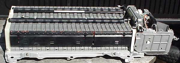
Prius battery pack (27kW, 202V)
source --- http://www.hybridcars.com/gallery/22070/photo
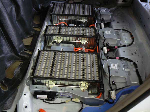
Toyota Highlander SUV NiMH battery pack (45kW, 288V)
right: three axial blowers to cool battery
source --- http://www.hybridcars.com/gallery/22070/photo?page=1
Lithium ion
NiMH provides
(roughly) twice the energy density of lead-acid, which was used used in
1997 GM EV-1, and lithium ion has (roughly) twice the energy density of
NiMH. So future lithium ion hybrids could get twice the distance on same
size battery pack as current NiMH hybrids. Well, not really, info on the
LG Chem site, a big Korean lithium producer, shows only a 1.56 advantage
in weight and 1.5 in volume per KW for their lithium ion battery over NiMH.
Lithium cells are 3.7V, so the cell count is reduced by a factor of three.
No standard chemistry
But a big
problem currently with Lithium Ion is that unlike NiMH, there is no standard
cell chemistry (or size). Every manuf has his own chemistry with different
tradeoffs. No 2nd sources, it's all custom. GM 'Volt' manager at a battery
conference recently said "convergence" (standardization) of Lithium Ion
is a requirement for electric cars.
Lithium ion spec
Neither LG
Chem or 123 Systems has the spec of its proposed Lithium ion battery for
electric vehicles online. However, 123 Systems does publish the spec of
a couple of their high current lithium ion batteries and the best of them
has about half the short circuit current of the Panasonic NiMH Prius battery
above (not a fair comparison, see below). At low temperature 123 Systems
publishes only the A-hr capacity. The short form data sheet does not show
ESR (peak power) vs temperature, which is possible red flag that
it may rise as in NiMH.
The highest power lithium cell data sheet I can find online is the 123 Systems 26650 (dia..length) cell (below). It's ESR must be non-linear. It's speced 10 mohm typ @ 10A, but on a discharge cycle graph (not shown) it 15 mohm. The lower right curve shows a 0.6V sag (it varies some with # of discharge cycles) at 40A discharge (@ 25C), which is an ESR of 600 mv/40A = 15 mohm consistent with the discharge cycle data. If the 15 mohm applies at still higher currents (not assured), then the short circuit current (Iss) would be 3.3V/0.015 ohm = 220A. This value for Iss is probably pretty close to correct, because the data sheet shows a 10 sec "pulse discharge" of 120A (curiously without specing the voltage).
Just as Panasonic specs their cell for maximum power out using a matched load, it would not surprise me if 123 Systems did likewise. And confirmation that is probably what 123 Systems is doing is that is that their pulse discharge current of 120A is pretty close to the calculated Iss of 220A. While 123 Systems doesn't spec it, the calculated (matched load) peak power out would be 1/4 x Voc x Iss = 1/4 x 3.3V x 220A = 182 watts.
Lithium
ion comparison to NiMH
A fair comparison
of lithium ion to NiMH can only be done by comparing either an equal weight
(or volume) of cells. I compare based on weight. Below is a comparison
of the Prius Panasonic NiMH module to lithium ion modules made by two companies
that feature nano technology (Altair Nano and 123 Systems). By putting
five 7.2V, 1 kg Panasonic NiMH in parallel and three 2.3V, 1.6 kg Altair
Nano in parallel they are pretty similar in voltage and weight. For 123
systems I used sixty 70 gram cylindrical cell in a series parallel arrangement.
I reduced the 123 Systems cell count by 20% to account for missing structure
a module would have.
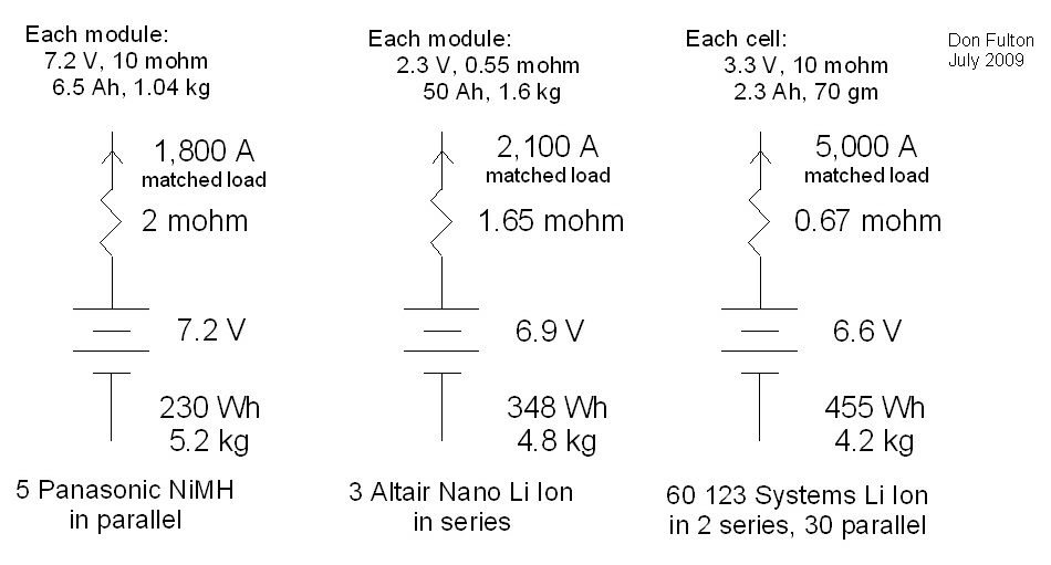
5,000 A (max) from 10 lbs of batteries -- pretty mind
boggling!
Paralleling batteriesx50
The biggest numbers above come from paralleling batteries, thirty in the case of the 123 Systems 5,000 A. Note while batteries can probably be paralleled, it's not obvious that this is allowed. The concern would be extra heat and wasted energy due to circulating currents if the internal cell voltages are not well matched. Voltage differences could arise from chemistry differences, temperature differences, aging differences, cycling differences. Very likely batteries to be paralleled should come out of the same lot (or be tested to insure their voltages match) and then be kept together so aging and cycling would be the same.
Panasonic NiMH
11.5 kwh
243 kw
Altair Nano Li ion
17.4 kwh
272 kw
123 Systems
22.8 kwh
619 kw
On an equal weight basis the Altair Nano lithium ion battery has (about) the same peak power capability as a NiMH battery and 50% more energy storage. The 123 Systems peak power is more than twice as high as NiMH and its energy storage is twice as high. There's no published data on ESR vs temperature, but the123 Systems 25C peak power is high enough that ESR could increase x4 at low temperatures and the battery pack could still deliver 150 kw (200 hp).
Altair Nano advertises that it's battery can be recharged in 10 minutes (123 Systems 15 minutes). The power calculations indicate this is reasonable (50 watts for 10 min in a 1.6 kg module). To fully recharge a 17.4 kwh battery pack in 10 minutes would require 6 x 17.4 kw = 100 kw (220 VAC x 500 A).
Whoops! 500A is far too high from 220 VAC. With the 70A or so limit (set by new cable standard for plug-in electric cars) a 10 min potential recharge time is extended to [500A/70A x 10 min] = 71 min, or 36 min if the 70A is pulled from 440 VAC. In other words although the battery can potentially be recharged quickly current limitations in the charging cable and also in high power/voltage distribution boxes result (back of the envelope) in full recharge times of more like an hour (220 VAC) to a half hour (440 VAC).The minimum operating temperature of both lithium ion cells (@ unspeced ESR) is pretty low (-40C Altair Nano and -30C 123 Systems).
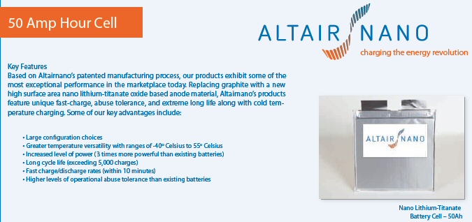
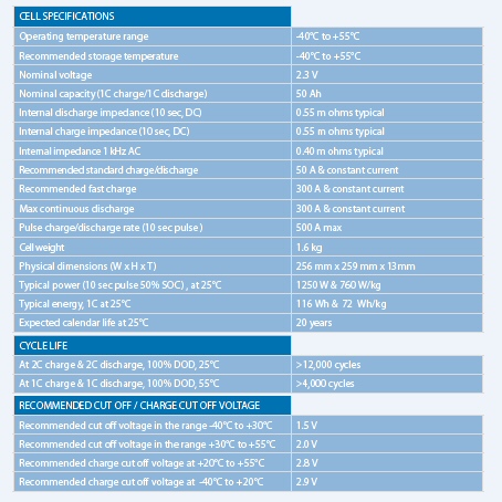
A123 Systems
A123 Systems
high current cylindrical cell
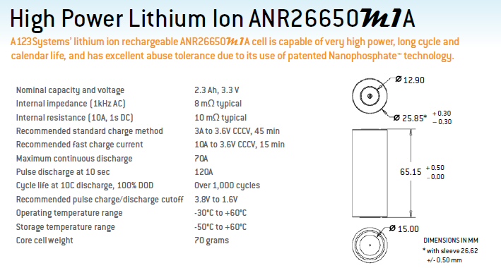
.
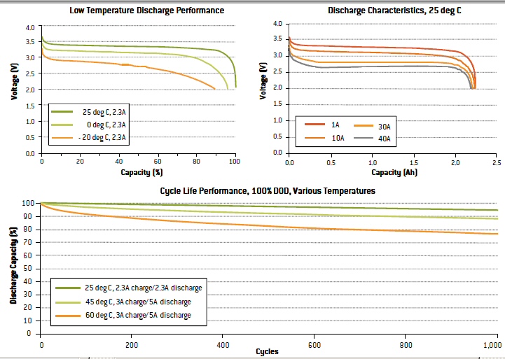
ESR (@ 25C) = 600 mv/40A = 15 mohm
Fisker Karma and A123 Systems
(update 1/1/12)
A123 Systems
20 kwh battery (Nanophase technology says Fisker spec) is being used in
Fisker Karma, which is just starting production (about 200 made). I now
find on the A123 site info on a battery pack they make for hybrid cars.
The sell the complete pack with thermal management and protection. It's
a good bet Fisker with limited engineering buys most of the technology
from A123, but maybe not the package, because the form factor in the car
is different from what I see in A123 photos.
A123 Sytems Battery Replacement (update 6/12)A123 lists a 23 kwh pack and 22.5 kwh was the original Fisker spec, but in production it has been scaled back to 20 kwh. The core cell is primatic AMP20, 3.3V 20 Ahr (66 wh). The nominal Fisker battery voltage is 330V (in spec), so they have some multiple of 100 of these cells. 20,000 wh/66 wh = 303 (close to what I found speced for Fisker), so clearly the Fisker battery pack is about 300 or so cells arranged in 100 x 3.
Don't know the details, but headlines are A123 Systems had to replace a lot of batteries (67million dollars worth!) delivered to Fisker Karma, which were made in their new Michigan plant because of some sort of quality problem. Apparently some of the Fisker Karma cars broke down due to the battery, including one being tested by Consumers Reports!"Consumer Reports finally posts Fisker review, finds litany of owners suffering from bad Karma"A real business set back for A123. News headlines describe A123 Systems as struggling as it reported a loss of 125 million in 1st quarter of 2012. A123 Systems is still under contract to supply batteries for a (pure) subcompact electric car coming from GM in 2013 (Chevrolet Spark EV), however, battery production at its Michigan plant has been halted.
Spec is 3C cont (10C 10 sec). C for AMP20 is 20A/cell, so 3C is 60A/cell and three in parallel is 180A. And 180A x 330V = 59kw (79 hp). So when the car is driven electric, the battery pack can deliver about 80 hp max (cont). My rule of thumb says 60 hp is about the wind resistance at 100 mph, but Fisker is a low sleek car, so probably can go faster.
Extrapolating from the smaller cyclinderical cell above resistance of 20Ah cell would be 1.15 mohm. At 3C (60A) this is voltage drop of 69 mv, and 60A x 69mv = 4.1W/cell. This is 4.1W x 300 cells = 1,230 watts dissipation for the whole battery pack when operating at its max continuous output of 59 kw. No problem here.
At peak levels from Fisker spec the battery pack must do 500A (150 kw) or 166A/cell. OK, the peak rating 10 sec is 10C, which is 200A/cell (10 sec).
Conversion of Prius to lithium ion
An independent
company (EDrive) sells a lithium ion battery upgrade for the Prius. The
1.3 kwh, 80 lb NiMH Prius battery pack is removed and replaced with an
EDrive 7.2 kwh, 200 lb lithium ion battery pack (2 in higher and 3 in longer).
The peak power demands on the battery pack are unchanged since it is set
by the inverter sizing. Hence each lithium ion cell can have an ESR that
is x3 or so higher than NiMH (on an equivalent 1.2V/cell basis)
and still provide all the peak power demands of the Prius electronics,
which were, of course, designed to match the much smaller NiMH battery
pack.
http://www.edrivesystems.com/faq.html
This upgrade costs 12,000 dollars (four hours of labor). The point of the upgrade is to make the Prius into sort of a quasi-electric. It's now plugged in to charge the battery, and since EDrive builds in (?) only a wimpy 1 kw (110/220 VAC) charger, the recharge time is speced at about six hours.
123 Systems conversion of Prius to lithium ion
Turns out
that 123 Systems makes a 5 kwh lithium ion battery pack specifically for
Prius conversion. Weighs 187 lbs. Conversion is done by HyMotion.
Apparently battery is allowed to fully discharge, it is not recharged by
Prius, only by plug in. It's not clear how its connected into the Prius
architecture, maybe through a diode? Recharge time @ 1 kw from 120 VAC
(only) is 5.5 hrs. There no real range spec, just says it "assists" in
all electric mode for 30 to 40 miles. There's a link (on 123 site below)
to a spec of the battery pack and what do you know the link is dead. Another
case of a lithium ion vehicle battery with a hidden spec.
http://www.a123systems.com/hymotion/products/N5_range_extender
Here is interesting data on the Prius with the 5 kwh battery added. It's four EPA city cycles (EPA city cycle is below). Gray shows the engine running. It's a 30 mile, 1.5 hr trip @ 19.5 mph av, which is four EPA city cycles in a row. On the fourth cycle the battery is exhausted, it's a normal Prius, and the engine runs a lot more of the time.
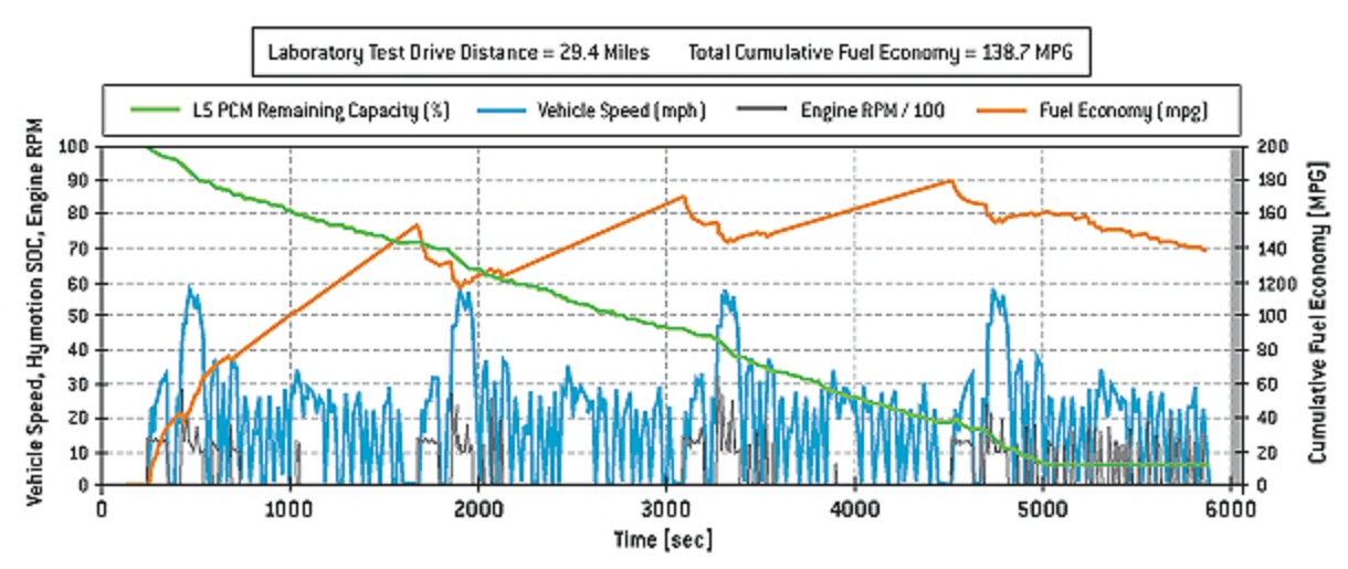
30 mile, 1.5 hr trip @ 19.5 mph av, which is four EPA
city cycles in a row
Prius with 5 kwh battery added runs mostly as
an electric for 3/4th of time (67 min),
then on last 1/4th it drives like a normal Prius.
Mercedes S400 Blue Hybrid --- Much ado about nothing
(11/2009)
The Mercedes
S400 Blue is the first production hybrid to use lithium-ion batteries.
It's on sale now in Europe and USA in 2010, but when you look in detail
at this car, so what? The press trumpets the battery doesn't take up room
inside the car; it's under the hood and even fits where the lead acid battery
used to go. Do you suppose maybe that's because its only 0. 7 kwh (truly
tiny). For god's sake a standard car lead acid battery rated at 75 ah means
it can put out [(75/20) A x 20 hr x (> 10.5V)] = > 0.787 kwh. That's right
the lithium ion battery has about the same kwh as a standard lead acid
battery, no wonder it fits in the same space! For perspective the Prius
hybrid has a 1.3 kwh battery. The Mercedes S400 Blue is heavy full size
car with a 3.5 liter V6 engine and costs about 88k. This is a 'mild' hybrid.
It's can't even go 2 or 3 mph on electric alone says the German engineer.
About all the 15 kw motor and battery do is quickly restart the engine.
Technically this does show that the peak current of lithium ion is pretty good, and says there should be no peak power issues with the much larger lithium ion battery packs in electric cars.
(Update 5/2010) Mercedes has a full page in New Yorker
for S400 hybrid
"Powered by"
a lithium ion battery.... God, marketing guys can spin anything. There's
going to be some disappointed Mercedes customers.
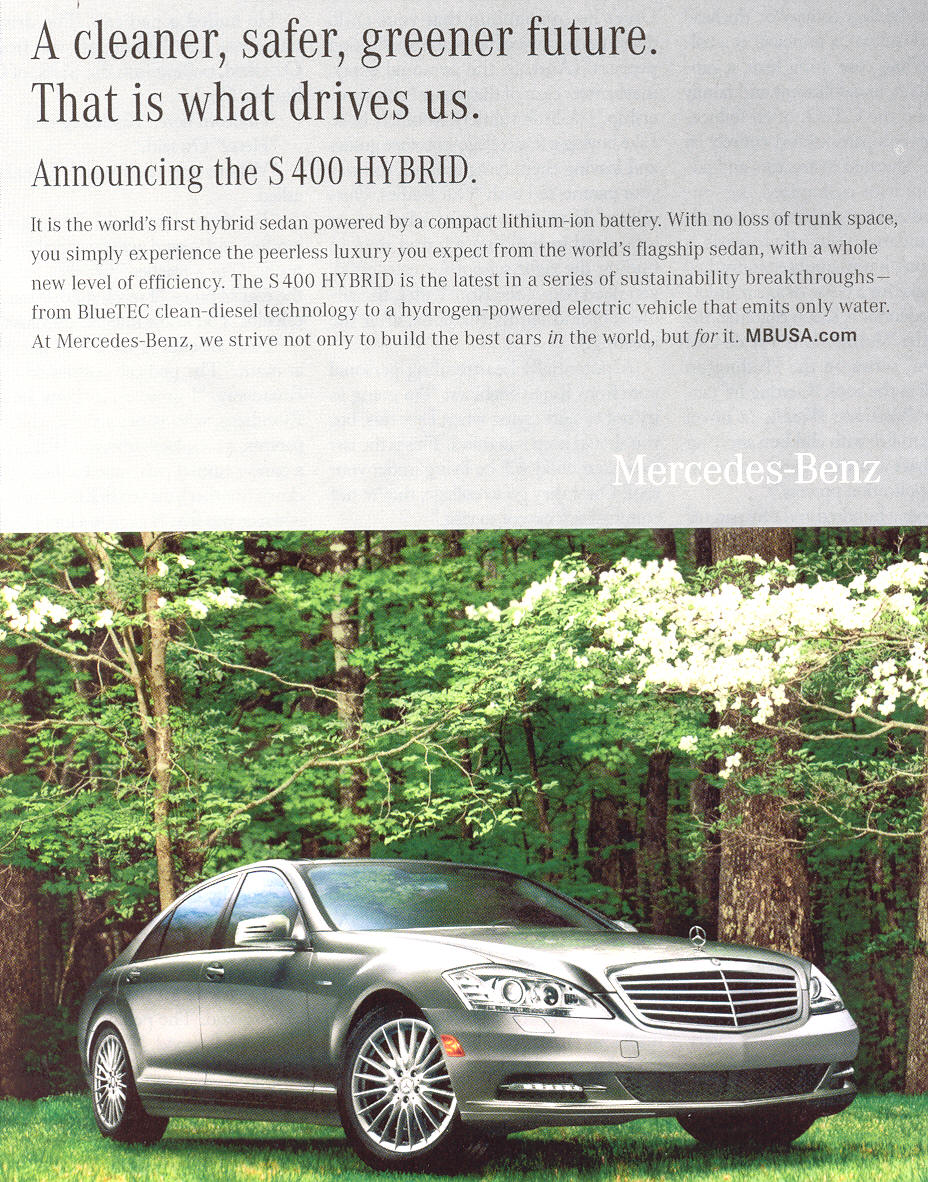
"First
hybrid sedan powered by a compact lithium ion battery"
"no
loss of truck space"
(May 15, 2010 New Yorker full page add)
Implications for GM Volt
Note the implications
of above for the GM Volt. The Volt is to use only 8 kwh of its 16 kwh battery
(for lifetime). Here 5 kwh battery is pretty much depleted in 20 miles,
and for maybe 15% of the time the engine is running. The implication is
that an 8 kwh (usable) Volt in EPA test cycle driving would yield less
than (8 kwh/5 kwh x 22.5 mile) = 36 miles range, whereas GM claims
40 miles. This partly explains the extreme emphasis put on aerodynamics
of electric cars, but isn't the Prius after a decade of evolution pretty
aerodynamic too? GM claims that aerodynamic changes alone to the production
Volt added 6 miles vs the concept Volt (but I'm not sure if the drive cycle
was specified).
Really high peak power
In the GM
Volt, which is planned to hit the market in Nov 2010, the engine will not
be coupled mechanically to the wheels. (Wrong!! This was GM marketing BS)
This is very different from all current hybrids, where both the engine
and electric motor are mechanically coupled to the wheels. Think about
what this means in terms of current and peak power that its lithium ion
battery must handle. It's really high!
I don't have hard numbers on the weight (see below) or hp of the Volt vehicle (nor of the battery pack, but for reference I'll compare it with my old mid-size Taurus, which weighed about 3,300 lbs powered by a motor rated at 200 hp (peak). To maximize the peak power to the wheels it's very likely that the Volt's motor's generator current ? power can be added to the battery current ? power. In round numbers this means that 50 hp of the 200 hp to the wheels comes from the motor with the battery pack delivering the remaining 150 hp. This is probably on the mark, because 150 hp x 0.74kw/hp = 111 kw, and this is the rating of the Volt motor and inverter.
(update) An early report (Aug 2008) out of UK that weight of GM Volt was expected to be 3,500 lbs.
Compare the peak electrical power needed from the battery pack in the Volt to a 'conventional' hybrid, the Prius. Even though the Prius battery cells are running at 180A the electrical power out is only about 36 hp. The Volt battery pack must deliver something like x4 higher peak power than the Prius battery pack.
Lithium ion paralleling
Initially
I thought this meant lithium ion cells for vehicles needed to have very
low ESR, lower than NiMH. I don't know if such lithium ion cells exists.
The lowest lithium ion ESR I have found (123 Systems) is an equivalent
basis x2 higher than NiMH (20 mohm for each 1.2V cell eq) But I now
see there's a work around. If the lithium cell battery pack has a high
energy storage (high kwh), then it will use lots of paralleling (or equivalently
the cells with have larger area). This kills two birds with one stone.
You gets lots more all electric driving range and the constraints
on ESR are loosened.
Very low cell ESR not required with large battery pack
For example,
if x6 paralleling is used (as I suspect it is in the Volt) then x3 higher
peak current/power can be delivered from the battery pack with each cell
have an equivalent ESR twice that of NiMH, which is consistent with
ESR of published 123 Systems lithium ion cells. So sort of as a freebie
with a large lithium ion battery pack sized for range, enough peak current
is available from the battery (perhaps with some supplemental current into
the inverter bus from the generator) to allow the design option of driving
the wheels only with the motor, dispensing with all mechanical coupling
from the engine to the wheels.
We can bound the battery pack volt/current peak options. The following combinations of V and A multiply to 111Kw (150 hp). Most hybrids today have battery pack voltages in the 160 V to 320 V range. Assuming the peak battery power is (like Prius) limited to 75% of the 'matched load' capability, we get:
200V battery pack
150 V x 750 A
300V battery pack
225 V x 490 A
400V battery pack
300 V x 370 A
500V battery pack
375 V x 300 A
Fire risk?
As best as
I can tell, what seems to be holding back Prius from going to lithium ion
batteries is fire risk. A year or two prior to the introduction of gen
III , Toyota said lithium ion was ready for gen III, but when gen III arrived
in 2009 it had NiMH. The fire risk assessment come for a few comments of
Toyota people. Who knows, maybe it's cost and weight too.
I read lithium ion batteries for cars will not be the same as for laptops, and the reason appears to be fire risk. If something fails in a lithium ion laptop battery, there is a run away oxidation --- translation: fire. Vehicle lithium ion use different chemisty with lower energy density to eliminate the run away condition.
Lithium battery chemistry
Lithium battery
chemistry looks complicated and initially I avoided the topic, but a long
article (now hugely revised) in Wikipedia gave a good overview. It argues
that electric vehicle people were interested in using lithium iron phosphate
(LFP) chemistry for their battery (LiFePO4). This is different from most
of the small lithium ion batteries used in computers and consumer products.
These are mostly lithium cobalt oxide (and some lithium manganese oxide
and lithium nickel oxide). The names refer to the material of the cathodes,
anodes are generally carbon (graphite). In other words in electric cars
iron is to replace cobalt, manganese and nickel.
The iron version of lithium ion batteries has only about 60% of the energy density of the other types, and it has other problems too (like high ESR). So why use it? Well iron is cheaper and more available than cobalt, but the big reason is safety, safety from fire. You can't have cars going up in flames at anything like the same rate as laptop batteries have gone up in flames. Iron also is better for the long lifetime and many cycles car batteries need. Drawbacks (besides lower energy density) is limitation on peak current (high ESR) both charging and discharging. An intrinsic lower peak discharge rate for iron may not be a problem for an electric car, because unlike a hybrid car, there is a lot more battery in an electric car, so each cell is much less stressed when the car accelerates. The Wikipedia article on A123Systems says its chemistry is LFP, which it is working to improve with nano technology.
Wikipedia gives these generic LFP specs:
Gravimetric energy density = >90 Wh/kg (>320 J/g)
Working voltage = 3.0V3.3 V
Let's check using the GM Volt as a test -- 16 kwh, cell weight of 375 lbs (170 kg)
GM energy density = 16,000 Wh/170 kg
= 94 Wh/kg
Ok (agrees nicely with >90 Wh/kg)
GM opts for lithium manganese phosphate
But then I
read that LG Chem that GM chose to provide the battery for the GM Volt
is not building LFP (lithium iron phosphate) batteries! LG Chem's chemistry
is Lithium Manganese Oxide. (This is hard to dig out. LG Chem says almost
nothing about their chemistry on there site.) Some sites painted the face
off between 123Systems and LG Chem for GM's business as a face off between
lithium iron phosphate and lithium manganese phosphate chemistry. Indeed
a GM executive said it was all about the chemistry.
One reference summarized the lithium ion battery chemistry this way:
There are four phosphate formulations from which to choose for a cathode material: iron, cobalt, nickel and manganese. Manganese is essentially a voltage compromise between the other three.It now (12/10) appears that Nissan has also chosen a similar battery (lithium manganese oxide) for its Leaf.
Apparently there is voltage signature to the chemistry. Lithium iron operates the lowest at about 3.2 to 3.3V whereas lithium manganese operate s little higher (3.5 to 3.6V). Below shows the discharge voltage of LFP (lithium iron phosphate).
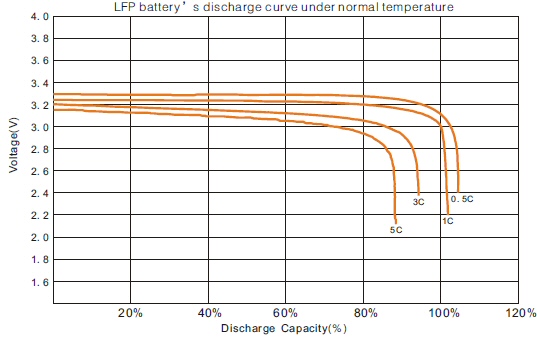
200 Ah LFP (lithium iron phosphate), 7.3 kg
source -- http://www.thunder-sky.com/pdf/2008926101921.pdf
Nissan Leaf lithium ion battery
Found some
early (2008) data on the lithium battery being developed by Nissan. Nissan
formed a joint battery company with NEC called Automotive Energy Supply
Corporation (AESC). Their cell is lithium ion with a (spinel) manganese
cathode (LiMn2O4). Cell voltage is 3.6V. In 2008 their prototype lithium
ion vehicle battery had these specs: (Wow, ESR goes up by almost a factor
of ten at -30C)
cell weight
527 grams
voltage
3.6 V
capacity
13 Ah (13Ah x 3.6V = 0.047 kwh)
power (25C, 2.5V) 1,086 watts = (434
A x 2.5V)
ESR (25C, derived) 2.5 mohm = (1.1V/434A)
power (-30C, 1.8V 116 watts =
(64 A x 1.8V)
ESR (-30C, derived) 22 mohm = (1.4V?/64A)
With this battery (L3-10) a 24 kwh battery would need 510 cells, which would weigh 592 lbs. The 2008 article quotes a Nissan battery engineer says they are going to increase the capacity to 30 Ahr to reduce the number of cells, then a 24 kwh battery would have 221 cells. This proposed larger cell is in the ballpark for Leaf which has [48 x 4] = 192 cells and a battery pack weight (with structure) 660 lbs.
At 90 kw output each of 192 Leaf cells is outputting 469 watts =(90,000/192 cells), or about 130 A per cell. Scaling the numbers above by (510 cell/192 cell) = 2.66, cell power at -30C is (2.66 x 116 watt) = 308 watts. This indicates that the peak power of the car with battery at -30C is rolled off by (at least) a third. We can also figure the battery sag at 90 kw, and at 25Cm, and it is very small (2.5mohm/2.66 x 130 A = 0.122 V, or a sag from 3.6V to 3.48V. This is a peak battery power dissipation of only (0.122V x 130A x 192 cells = 3.04 Kw), or about 3% of the delivered power.
Comparison
of Volt and Leaf lithium battery thermal management (12/15/10)
My nephew
asked me what was new with the Volt, so here is my reply covering [Volt
= hybrid] and summarizing how Volt and Leaf are handling the thermal issues
raised by the lithium ion manganese batteries they are both using.
The Volt and Leaf are on the threshold of deliveries (1st Leaf has been received by first individual customer in USA), yet much of the detail of the drive trains are still hidden, no info on battery voltage or type of motor. But some details are dribbling out.
The biggest news revealed a couple of months ago is that GM has been lying, and the Volt is not really an electric car. It is a hybrid. It has the same three shaft planetary gears as a regular hybrid, which allows the engine and the motor torques to be combined to drive the car, and they do this in some modes like at high speed when the battery is flat. This has lots of performance advantages, but adds the cost of a big gear set and a whole bunch of pins and clutches to allow them to switch the engine in and out mechanically.
Another interesting fact I just found out this week. The lithium battery the Volt and Leaf are both using is a delicate thing. If you run it just a little warm (> 72F) or cold (?32F) then you degrade the battery lifetime, which is a major concern of both GM and Nissan, because the battery is so expensive its capacity has got to hold up for the life of the car. They are allowing for a 20-25% capacity loss after 8 to 10 years.
GM Volt has a real edge here. Volt has an engine, so if the battery is hot or cold, the engine comes on and the car runs as a hybrid, not as an electric, even though the battery may be charged. Virtually no one in the automotive world seems to have figured this out yet! GM also has well insulated the battery and uses an expensive liquid heating/cooling system to hold the battery temperature when running in a very tight range (70F +/- 2F). Good for battery, but it eats away at electric range, because if your car is parked in hot sun, the battery air conditioner will come on to keep the battery cool and the power to run the air conditioner is being drained from the battery!
Nissan with the Leaf is sticking their neck out that the battery will hold up, or people won't care if it degrades in a few years. They have no engine to protect the battery. When you run the car, the battery has to be used regardless of hot or cold it got when it was parked. Also they have no fancy heating/cooling system for the battery. All they have is one miserable fan to air cool the battery. Keeps the car cheap, but time will tell if this was a smart or dumb decision. Some people think they have under engineered the battery pack. Ford is going to use a Volt like active temperature system and even Nissan is now saying in 'higher end' electrics or in cars for the Middle East, they will use it to.(update Oct 2011)
(update 2/13)
Tesla in their first
electric car (Roadster) used a liquid cooling system for the battery. Don't
know what they are doing for their 2nd car (Model S sedan).
Battery coolant
problems (update 1/10/2012)
Real world
problems of liquid battery cooling my have reared its head. Most new electric
cars are liquid cooling the lithium ion battery, the Leaf being the big
exception. But what happens if there is a battery coolant leak? Of course,
the same question can be asked about coolant leaks in normal gasoline engines,
but there is over a century of experience in their design and use.
The known facts are these: Volt has recently recalled all of its 8,000 or so Volts to do something they call strengthening the battery container. Fisker Karma has recently recalled all of its 250 or so cars because of a possible clamp problem allowing battery coolant to leak apparently into the battery container. The Volt recall was prompted by a fire (and 2nd almost fire) in cars sitting weeks after being crash tested. The facts are a little unclear, but the claim is the battery cells were not directly damaged, so the suspicion is that the battery coolant system was damaged.
I suspect the problem may be this. The battery containers are probably a full of little and big circuit boards that make up its monitoring and protection system. And of course the coolant is flowing all through the battery container to get the heat out of every cell. Hence the problem, I am guessing, is that a leak of the coolant is more likely than not to be into the battery container, and (if they are not well sealed) onto those circuit boards. My memory is this was specifically mentioned in the case of the Karma recall, and could explain the otherwise mysterious catching on fire of crash tested Volts that had been sitting in storage for weeks.
quasi-electric GM Volt
----------------
Seeing a Volt (update 11/27/11)
I saw my first Volt
today and had a chance to talk to the driver. Volt was plugged in to one
of two electric charging stations (installed by US dept of Energy) directly
in front of Boston City Hall. Clearly the charging stations had been positioned
for publicity as an electric car to be charged needs to be parked in a
'no parking' area on a sweeping curve on a busy downtown Boston main street.
I was surprised the sign on the chargers said "free" charging. The driver,
who said his company was testing the Volt, said well 'free' means paid
for by taxpayers. Also surprised that the cord was part of the charging
station. Noticed another weirdness. The Volt charging plug is not conveniently
located for on-street charging. With the car parallel parked (as here)
the plug is on the drivers side near the front door and near traffic, so
the long cord from the charger has to be run around the car to reach the
plug.
The Volt is quite a small car and tight inside. The driver commented there was not much head room. He said it had a lot of pep. I was standing next to it as he drove away, and it was nearly silent (no traffic on a Sunday night).
Electric ? quasi-electric car sales (11/28/11)
(1/14/13)
A total of
9.5 million new vehicles had been sold in the United States this year through
October.
* G.M. has sold 5,300 Volts since introducing the car a year ago in late
2010
* Nissan has sold 7,200 all-electric Leafs in the first 10 months of this
year
* Tesla has sold about 2,000 electric cars since 2008
update (1/14/13)
* GM has sold 23,000 Volts (and announced a luxury Volt to be sold as a
Cadillac will begin production late 2013)
* Nissan has sold 10,000 all electric Leaf (about half of what they had
hoped to sell)
Fire risk (11/28/11)
Collision
damage to the Volt battery back has shown it can catch on fire. Hard to
evaluate this risk at this point. In the inelegant phase of GM spokesperson,
This is a postcrash activity." A crashed Volt sitting in storage recently
caught on fire 3 weeks after the crash. A real slow motion problem.
Three Volt batteries were then damaged (but how badly is not described)
and one caught on fire and one smoked. Fire risk with large lithium ion
batteries has long been a serious concern, just look at the recall of laptop
batteries for possible fire risk.
GM is sort of covering up the weakness. Look at this statement, "A pressing issue, (GM spokesperson) said, is ensuring that batteries are de-powered by trained service personnel after a collision". In other words GM is sending out people to discharge the batteries after an accident or crash testing. This is equivalent to drain the gas out of the tank of a crashed car, which I suppose is sometimes done.
It might seem that electric cars could benefit from a discharge resistor built that would be activated by a crash, but the problem is the heat and time it would take. A 1.5 kw resistor running at room heater power levels would take about 10 hours to discharge a Volt 16 kwh battery. An external 10 kw load bank (33A at 330V), which emergency personnel could provide, could do the job in about an hour and a half.The real answer is to robust the protection devices (fuses, etc) within the battery pack and/or change to a lithium-ion battery chemistry more tolerant of damage. I can guarantee you that GM is now working on this. There has long been a 'nail damage' test and spec for small lithium-ion cells.
Consumer Reports says that the Volt it owns (cost 48k because the dealer slapped on a 5k premium charge!) and is driving in Connecticut this winter (we are not talking northern Minn here!) is only getting 25 to 27 miles electric range. One third of the electric driving range is lost at moderately low temperatures (southern NE winter) Consumer Guide borrowed a Nisson Leaf and reports it "it also gets very short ranges in very cold weather".
(update 2/22/12)Consumer Guide also points out another tradeoff with electric cars: the heater. Heat for the passenger compartment is basically free in a conventional car, but is a really battery drainer in an electric car. The answer of the Volt engineers was to focus on heated seats. Consumer Reports doesn't like it, saying while it keeps your body warm your hands and your feet freeze. The Leaf heater is powerful, but you pay for it in lost range.
NYT article about 2nd BMW all electric on road prototype (ActiveE) says test drivers found as much as 40% range loss in cold weather with their first on road prototype (MiniE). Consequently BMW went to liquid heating/cooling of the battery, though I'm not sure how much this helps since the power to heat the battery has to come from the battery!
Consumer Guide (as others) are finding Leaf projection of available miles to be worrying and somewhat flaky. It's probably (as implemented) a bad idea. What Nissan is probably doing is extrapolating range from the incremental power use. This would lead the to the range jumping all over the place (as below).
"On one commute, his range in a Leaf was at 43 miles when he turned onto an eight-mile stretch of highway, but it fell from 43 to 16 miles after eight miles at 70 mph. If it keeps on going down at this rate, will I get to work? Champion said." (from Consumer Reports)-----------------------
1) Many types of Li-ion cell cannot be charged safely below 0C (32 F) (Wikipedia)
2) "Right now we're thinking (below) 0-10?C (32F to 50F) we won't use the
battery"
(Jan 2009 article quoting head of GM battery development for Volt)
What! It's an electric car with a range extender engine and at low temperatures "we won't use the battery". Give me a break --- And this is supposed to a practical car?GM liquid cools the battery to keep it from getting too hot, but what about winter? GM battery people say if the car is plugged in then the heat from the charger will keep it warm. Really? I suspect strongly the battery controller pulls line power for heating. (Yup, see below) This has got to be a lot of power, the battery weighs 400 lbs and is spreadout in big T structure under the car. Of course, no mention of how much power this is. The spec on the line cord standard used is 70A, 240 VAC. The math shows this would fully recharge the battery in 1 hr (GM says 3 hr). So you plug it in at 6:00 pm and its fully charged by 9:00 pm, it has enough residual heat to keep it warm until 8:00 am next morning. I don't think so. I'm extra suspicious because GM doesn't frankly admit the battery needs to be heated in winter, they use the euphemism "conditioning" the battery.(update12/10 --- If car is unplugged for a long time in cold weather and battery gets cold, then Wikipedia says the car runs on the engine (no hybrid peaks?) until the battery warms up. So what will the Leaf do!!
"Another of the weaknesses of electro-chemical batteries is degraded performance when they are very cold. GM engineers have devised battery conditioning algorithms to help overcome this." ('Conditioning will be the key to battery performance and durability says GM', article Jan 29, 2009)Volt battery thermal management system (update 12/14/10)Asked about battery performance in cold temperatures like North Dakota, GM battery guy notes it's a "self correcting problem", ESR goes up at low temperatures, he says, so the battery generates more heat internally. Well that's one way to look at it.
So what is the Leaf going to do? With no engine they have to use the battery whether its warm or cold. Do they use a different lithium battery chemistry?
The Volt battery cooling/heating system keeps the battery temperature in a very tight range of 70F +/- 2F. Sure enough if the car is plugged in then the heating/cooling power comes from the grid. If the car is parked (not plugged in) in hot weather, then interestingly battery power is used to run the battery air conditioner, so just parked the battery will be running down. They limit how much the battery discharge in this mode to 75% of capacity. Below this capacity the cells heat up sitting parked in hot weather. They do not run the battery heater when parked in cold weather. The cells just get cold, and then the engine runs when the car is started if cells below 32F. This battery temp control strategy is going to get a good try out, because in 2011 (or 12) the car is to be widely sold in Canada. The problem with high temperatures is battery lifetime. It's 8 years at 70F, but only 5 years at 90F.
If the battery is above 122F or below -13F, then the car simply will not run!! until the battery heater/cooler can bring the battery temperature into line. Posters understanding is that a cold soak forces a plug-in to recover, which sound ridiculous to Canadian posters who think they may come out of work on a cold day and be stranded. One of the key issues which no one has data on is how good is the battery insulation and what is its temperature response time. They are guessing the insulation is good enough that battery temperature will remain below 122F after being parked 8 hours in the Arizona sun.
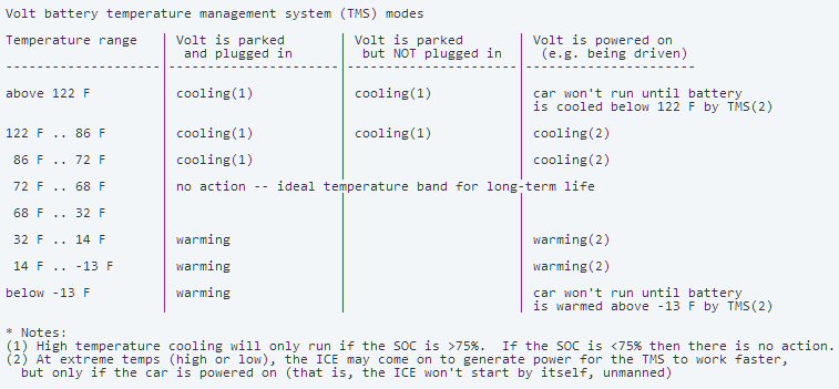
Summary of GM Volt battery thermal management unit
(heater/cooler)
posted by ChrisC at link below 12/12/10
Details of the Volt battery thermal management system
here:
http://gm-volt.com/forum/showthread.php?5243-Volt-thermal-management-system-temperature-band/page12
Winter commute
But it seems to
me the crux of the winter problem is this: You buy the car to commute 10
to 15 miles to work and back. With the touted 40 mile all electric range
you expect you can run the Volt in all electric mode using only a home
charger. But what happens when the car sits outside at work for 10 hours
in winter not plugged in? Unless power is bled from the battery to self
heat it (which I suppose is a possibility), the battery pack will be at
the ambient for the commute home, and according to tidbit 2), if the ambient
is below 32F (or maybe even 50F), the battery in your electric car is not
just weak, it is totally unusable!
Now you can still get home because the engine/generator can put out 70hp (generator rating), but the car is horribly underpowered. With the battery unusable it's not a hybrid, it's just a heavy 3,500 lb car with a 70 hp available for acceleration!
GM confirms cold temp problem (update Jan 2010)Both LG Chem and GM are withholding the battery specification. Why? (I don't understand GM's comments above about not using battery below 0C (or 10C). Is it related to charging? LG Chem lithium ion batteries have a discharge spec at -10C and 123 Systems gives their min operating temperature at -30C.)
After writing above, GM answered a question about cold battery at work at the opening of their new battery plant. Their (crazy?) answer is that the car will run on the engine until the battery warms up! So the GM bullshit is if you drive less than 40 miles a day, meaning you live within 20 miles of where you work, then the Volt will operate as an electric car. Now we find out that's not true in winter!. It's a half electric, returning home your not driving an electric car.The crazy part of the GM answer was the engine runs 'until the battery warms up'. Well just how is it that the battery warms up? The only efficient way for the battery to warm up is if they are running the hot engine exhaust gases through the battery enclosure. I supposed it's possible, but I bet this is a nightmare in terms of corrosion, etc. So my guess is that the battery is being heated electrically. Either the battery is help powering the car and is heated by ESR loss, or more likely, current from the generator is used run a heater in the battery compartment. And just how many watts is this and how long does it take for the battery to come up to temperature? Surprise, of course, GM doesn't say even though it damn well knows because the battery is now (supposedly) in production.
GM Volt design overview
(update 10/11/10)
Finally what looks to be a reasonable detailed spec for the GM Volt has
appeared (below).
http://gm-volt.com/full-specifications]
It includes some new info like (finally) the capacity of the gas tank (9.3 gal) and cooling capacities of the battery and electronics and the number of battery cells is finally disclosed (288). Revealing is that the EPA city range is now given as 25 to 50 miles electric, not 40 miles always claimed by marketing. Charging times are given, but are meaningless since the charge kwh is not given. The numbers alos look funny. If 8 kwh is the maximum allowed discharge and since 1.5 kw can be pulled from 120 VAC with a good charger design, then an 8 kwh charge should only take 5 1/3rd hours, not 10 to 12 hours!
Spec
battery (LG Chem)
16 kwh, lithium ion
288 prismatic (10/11/10), 3.5 V? cells (arranged how?)
(220 cells 12/10 Wikipedia )
liquid cooled
436 lbs
built-in charger
3.3 kw (7/10)
usable capacity
10.4 kwh (25% to 90% capacity)
originally 8 kwh (30% to 80% capacity)
(update 10/8/10( GM is now saying 'somewhat more' than 8 kwh
will be used, possibly 10 kwh. Also as the battery ages the
usable fraction of the battery range will be expanded to prevent
milage range from shrinking. Oct 13, 10 PopSci test driver
says 65% of battery (10.3 kwh) is "customer usable" and
Wikipedia now says 10.4 kwh
motor
111 kw (150 hp), PM
Technical SAE paper by GM engineers says Volt motor and generator
as PM (not induction as earlier suspected)
272 ft-lb (368 nm) torque
generator
54 kw (72 hp), PM
max speed
100 mph
0 to 60 mph
8.8 sec
(Leaf at 424 lbs ligher with 80 kw motor is 10.0 sec)
cooling (liquid)
battery pack
7.4 qt
generator
7.7 qt
power electronics 3.1 qt
engine
1.4 L, 4 cyl
(GM Family 0, 1.4 L, 4 cyl, 66 kw, 90 hp @ 5600 rpm)
GM specifies premium gas!
wheelbase
105.6 in (midsize = 108, full size 112)
weight
3,790 lbs (10/11/10), earlier estimated as 3,500 lbs whoops!
(424 lb heavier than 3,366 lb Nissan Leaf)
gas tank
9.3 gal (10/11/10)
9 gal says Consumer Reports (6/28/10 update)
engine mile/gal (implied) 32 mpg = [(340 miles
- 40 mi electic)/9.3 gal tank]
Popular Mechanics measures 32 mpg city, 36 mpg highway
charging
110/220 charger built-in (Connects direct to line
via SAE J1772 cable)
10-12 hr @ 120 V (how many kwh?)
4 hr @ 240 V (how many kwh?)
EPA city range (EV mode) 25 to 50 miles electric
(varies with terain, driving style, and temp)
Popular Mechanics got 31, 33, and 33 miles EV in test drives
For reference gen III Prius: 106.3" wheelbase, weight 3,042 lbs, 98 hp (1.8L) engine)
Test drive --- Popular Science 10/13/10
Car drives the same in all modes. Transistion between modes almost imperceptable.
Engine can barely be heard when it's running slow. In charge depletion
mode the car runs as a hybrid, so acceleration is from battery, followed
by engine RMP revs increasing as the generator works to not only power
the car, but to recharge the battery back to the nominal hold voltage.
This decoupling of the engine noise and its lag after acceleration takes
some getting used to. Their biggest disappointment is that gas milage in
charge depletion mode they measured (just 38 miles) to be 37 mpg. It is
a heavy hybrid.
Estimate of peak acceleration power
(update ---
The analysis below assumes the Torque vs Speed profile of the car is approx
rectangular, making the power vs speed shape triangular. This may or may
not be true for the Volt. The peak hp of 141 hp is within the capability
of the motor assisted by the geneator (working as a motor), but another
way to boost accleration time with limited power capacity is to have a
wide contant hp range in the motor. This is what I suspect is done in the
Leaf.)
With the weight of the GM Volt speced and 0 to 60 mph time (To) measured, a (rough) esimate of peak (acceleration) power to the wheels can be made. The simplest model is constant torque leading to a linear ramp of velocity with the maximum power point (Po) at 60 mph. This mades the energy delivered to the mass of the car during the acceleration
m = 3,790 lb/2.20 lb/kg = 1,723 kg
v = 60 mph = 26.8 m/sec
To (0 to 60 mph) = 8.8 sec
E car kinetic = 1/2 x m v^2 = 1/2 x Po x To
= (1/2) 1723 x (26.8)^2
= 619 kj
Po = (m v^2)/To
= (1,723 kg x 26.8 ^2 m/sec)/8.8 sec
= 141 kw
Po = 141 kw is a very interesting answer (if on the high side). But it's reasonable since it is within the kw range of the drive train. It requires (as I suspected) that both the main 111 kw motor and the 54 kw mot/gen are being used to accelerate the car. From another view point @ 60 mph the car has acquired 619 kJ of kinetic energy. If the power pulse was rectangular, this power would come in half the 8.8 sec (0 to 60 time) or 4.4 sec, so this makes the peak power (Po) = 619 kJ/4.4 sec = 141 kw.
Let me list the design challenges.
Heavy, expensive battery pack (400 lbs, 700 lbs with structure)
New battery technology, chemisty still being tweaked
Battery lifetime issues due to relatively deep discharge (compared to hybrids)
How much battery protection is needed/tradeoff with energy storage
High power inverter (or smaller parallel inverters like Tesla?)
Battery ESR increase in cold weather limits peak power
(or problems with lithium ion chemistry in cold weather)
Large PM motor (shift from PM to induction to handle heat?)
Motor if PM cannot allowed to get too hot.
Peak power rolls off if hot
Overtemp trips disable car (unlike hybrids
there is no back up with direct engine to wheel)
Engine noise ? vibration not correlated with vehicle speed or torque
Line recharge ports (separate converter with 120 to 240 VAC range?)
(480 VAC not mentioned)
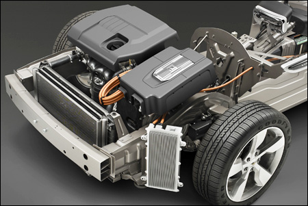
GM Volt at auto show (spring 2009)
Very strange, why isn't the 4 cyl engine exposed as in
every other car,
a mechanic will need to go on an Easter egg hunt to find
it.
Is that double radiators in front?
40 miles on battery alone?
Volt has been
widely touted by GM as able to go 40 miles without the engine turning on.
Now GM says well it's 40 miles (what speed, what terrain?) with all
accessories turned off, so it's no heat and no A/C! Notice in
the specs the generator hp rating (72 hp) doesn't match the engine hp rating
(90 hp), which on its face is odd. This may just be rating conditions,
or it could be a real mismatch because the engine is an available engine,
whereas the generator would be designed for the Volt. If current from the
72 hp generator can feed directly into the inverter, which I assume it
can, then at peak motor/inverter power (150 hp) peak power demand from
the battery is 78 hp (58 kw). Electrically for the battery 58 kw (peak)
means for x2 paralleling [58,000 = 315V (= 200 cells x 3.5 V x 0.9 sag/2)
x 184A] or for no paralleling [630V x 92A].
Tragic flaw?
Some posters
to Volt articles think the Volt has a tragic flaw. After its battery runs
down, it becomes a heavy car (est 3,500 lbs) with a 1.4 L engine. "It will
be very underpowered", said one poster. This thought flashed through my
mind too, but it's hard for me to judge from experience, it needs to be
calculated. In all non-hybrid cars the engine is sized for the peak power
demands, the worst case may be accelerating up a hill.
Infinitely variable transmissionHowever, in terms of engine hp the Volt is not very different from the Prius (or most hybrids). These cars have small battery packs, so on the highway they run entirely on engine power. The Prius gen I and II had a 1.5 L (70 to 76 hp) engine, but it's been increased to 1.8 L (98 hp) in gen III. On the other hand the 2010 Ford fusion hybrid has a 2.5 L engine. The Prius is a pretty small car with a light battery pack (100 lbs or so), so 1.4L for the Volt does look pretty small.
However, what probably is not understood by the poster and most people is that this car has, in effect, a infinitely variable transmission. The inverter provides all the current to the motor which in turn provides all the torque to the wheels. At low to moderate speeds the inverter can always fully torque the motor even if only limited power is available from the generator/battery, because power = [torque x speed]. So in cold weather even if the car has to run on engine power alone (probably unlikely), the car will still accelerate from a stop normally up a highway ramp only beginning to die when the car gets to higher speeds where it needs to merge, and just a few seconds of hybrid peaking from the battery would solve this problem.
but, but ... GM is saying the control strategy with the engine is to hold the battery capacity at 30% on extended drives. I suspect they will allow a small variation around 30% to get extra power for accelerations to mock hybrids. It wouldn't take much in the way of capacity change (few percent) since their battery pack has more than x10 the size of a typical hybrid.
It is a hybrid (update 7/10, 12/10)
GM recent
releases confirm that when running on the extended range engine it works
like a hybrid. With such a huge battery there should be plenty of juice
for acceleration. The engine (80 hp) has just enough (av) power to overcome
air resistance at its 100 mph (rated top speed).
In Oct 2010 the story from GM said only that the engine would be mechanically coupled to the wheels in charge depletion motor above 70 mph. By Dec 2010 the story has changed again. Now Wikipedia says in charge depletion mode engine will sometimes (acceleration) mechanically drive the wheels at speeds of 30 mph to 70 mph, and above 70 mph it drives the wheels all the time.
Volt cost (update Jan 2010)
GM executive
speaks the truth about their 40k car ---
Its going to take us three generations of range-extended electric vehicles to get any anywhere near reasonable costs, said Thomas Stephens, G.M.s vice chairman for product development. But if were going to have to be ready for the demand in 2020, we have to be out there by 2010 with the first generation.2nd battery in GM Volt
Wind resistance power
One poster
says continuous highway speeds only require about 47 hp. Since wind resistance
rise as speed^2 and power = force x speed, power needed to overcome wind
resistance rises as speed^3. Considering only wind resistance it takes
237% more engine power to cruise at at 80 mph than at 60 mph. My scaling
of Prius data (confirmed by Wikipedia) is overcoming wind resistance takes
about:
13 hp / 9.7 kw @ 55 mph
17 hp / 12.6 kw @ 60 mph
40 hp / 29.6 kw @ 80 mph
57 hp /42.2 kw @ 90 mph
79 hp /58.5 kw @ 100 mph
Conclusion: for a car with a top speed of 100 mph, like GM Volt, the minimum engine size is 80 hp, and surprise, surprise the GM Volt engine at 90 hp is just above the 80 hp wind resistance minimum.
Lithium ion cars hit market?
"G.M. Says Chevy Volt Is Still on Track (delivery in late 2010)" (June
2009) By Oct 2009 they will have 80 built as pre-production test and advertising
vehicles. Estimates are it will cost 45k or more, and it looks like a small
car!
I read in later 2010 Toyota is planning to sell some lithium ion vehicles to fleet buyers. (Aug 09) GM will also be delivering 125 Volts to electric utilities in Virginia for testing prior to Nov 2010 launch. US dept of energy have given GM 30 million for testing of Volt (125 fleet and 500 customers), which is a subsidy of 46k per vehicle. In other words our government is effectively buying the cars and giving them away!
Volt at low temperature
GM marketing
repeatedly claims: "Volt is designed so the first 40 miles of driving are
powered by the electric energy stored in the battery." But it now turns
out that's not true in cold weather. GM chief engineer has confirmed that
at low temperatures the engine will run to supplement the battery. At low
temperatures, this car is somewhat like a modern locomotive, where the
engine runs a generator and the generator powers the motor.
The lithium ion battteries probably weaken at low temperatures. My guess is the main worry may be large increases in ESR at low temperatures, as in NiMH, dramatically reducing the peak power.
Wikipedia (GM Volt) has the following vague low temp stuff, which is pretty vague but scary enough to say this is California type car!
"The battery needs a minimum temperature of between 0?C to 10?C (32?F to 50?F) (well thats' precise) to be used and when the Volt is plugged in the battery will be kept warm enough so that it can be used immediately when the Volt is unplugged.The Wikipedia footnotes a Jan 2009 interview with GM battery engineer, which says the following:.** If the Volt is kept unplugged, and the temperature of the battery is below the minimum temperature the gasoline engine will run until the battery warms up. This temperature regulation is done since electro-chemical batteries have degraded performance when they are very cold."
-- "While the vehicle is plugged in to charge, the battery inherently heats up and the cooling system will keep it at optimal temperature. If the ambient temperature is too cold, the battery will be pre-warmed in order to allow the car to operate on electricity as soon as it is unplugged." (Whoa! How much power does it take to keep a long 400 lb T shaped battery pack warm?)
-- "Right now we're thinking 0-10?C we won't use the battery." (ambiguity #1: does this mean 0 to 10C or does it mean somewhere between 0C and -10C. It reads the former and this is how its quoted in Wikipedia, but my guess is it's more likely to be the latter.)
So here is the GM chief battery guy saying in early 2009 that the battery may not be used if it's temperature gets below some threshold. But this statement is also not clear. Does he mean not used at all, or does it mean not used for range, but can still be used for a few seconds during acceleration like in a hybrid?
Not used at all?Charging battery with onboard generator (update 11/24/09)
If the battery is not to be used at all in cold weather then 0 to 60 mph time is probably going to be pretty bad. The engine/generator can only put out 70 hp the generator rating (though the generator might be able to pass the 90 hp from the engine for a few seconds). At low speed the torque will be OK because full motor torque is available, but as speed picks up the 70 hp limit will cut in and acceleration is going fade. Operated this way the car would likely be a real pig.Another way to look at it is this. The maximum power from the battery pack in all electric mode must be 150 hp because that's the rating of the motor. The power from the engine/generator is only 70 hp, so the power for acceleration is halved if the battery is not used at all.
So I doubt this is going to happen, performance reasons would force GM to operate the car in cold weather more like a hybrid. Even with high ESR in the batteries in cold weather, my guess is substantial peak battery power should be available to assist the engine during acceleration because the battery pack is so large (more than x10 a hybrid).
"The onboard generator will not charge the Volts battery. Its function is to maintain the battery charge at a predetermined level so that the car can keep moving after the battery has run down at about 40 miles. This is a deliberate choice on G.M.s part charging from a plug-in connection is far less expensive."Why is this forbidden? Sure you probably can't recharge at x35 the 110 VAC rate because the ESR losses in the battery would be almost a thousand times higher, but surely you should be able to recharge faster than line charging . This might be neat way to both warm and recharge the battery in the morning while eating breakfast. One lithium-ion battery manuf claims his batteries can be recharged in ten minutes. To forbid this seems incredibly stupid to me. Here is my posting to this NYT article covering low temp problem, the onboard charging issue and performance when the battery is depleted.
post 43
GM is not being honest about the battery low temperature performance. Look at the euphemism (conditioning) GM uses for heating the battery. Denise Gray of the GM battery development team was quoted in early 2009 saying, right now were thinking 0-10?C we wont use the battery. Its got to take a lot of energy (and time) to heat 700 lbs of battery. Will the line power used to heat the battery be included when the cost to run the car is figured? Dont count on it.
Seems to me absurd that the user is not going to be allowed to charge the battery using the onboard generator and engine. The generator is rated at 53 kw. This is x35 more power (!) than the 1.5 kw the 110V AC line can deliver.
I wish Mr. Brooke had explained how good performance was maintained when running on generator. My guess is that when charge drops to 30% the car converts in effect into a hybrid. Its large battery at 30% charge would have much more peak power reserves than a conventional hybrid car battery at 90% charge. Donald E. Fultonand next day I posted this:
post 49
On recharging the battery on a cold morning with the on-board generator:
All batteries have some series resistance (ESR) and in cold weather in addition to the battery capacity dropping the ESR will increase substantially. Heat dissipation in ESR (I^2R) varies as the square of the current. The onboard 53 kw generator can supply a ton of current, so on a cold morning it should be able to both recharge and warm the battery in not much more time than it takes to eat breakfast.
This is pretty handy if either you forgot to plug in, or there was no place to plug in. So why is GM going to prevent this? Donald E. FultonVolt engine speed
What is going on here? Why is the engine speed varied? Maybe this is the answer (from an article in ESD magazine)
" The peak efficiency of the internal-combustion engine, however, is only 30%, and the average efficiency is about 12% at high revolution-per-minute rates."So if the battery pack has lots of charge, maybe the engine is run slow where it's most efficient. But if the battery runs down or its cold, then you need hp from the engine ? efficiency is secondary. It's then necessary to crank up engine speed to increase the hp.
GM Volt on front page (update 7/29/10)
GM Volt on
front page as price of 41,000 (base model) is announced. They will begin
deliveries in late Nov 2010 as promised, but production levels scheduled
for 2011 are very low (10,000) with 2012 production set for 45,000. Going
on sale in a few months, but no specs and no mil/gal estimate! They still
just say the battery has "more than" 200 cells.
Instrument panel has a 7" touch screen and the car has a 30 Gb hard drive (for audio storage)!! Charge times given as 10 hr @ 120VAC and 4 hr @ 240 VAC, but material on the ChevroletVoltage.com site which supposedly has the specs gives the charge time as 8 hr @ 120VAC and 3 hr @ 240 VAC! Battery is liquid cooled and heated. Comes with a 120 VAC power cord. Four seats (battery pack prevents a bench in rear). 8 yr warrantee not only on battery, but on the whole electrical drive system. The car will initially be sold in seven states, but it includes hot and cold states: Texas, Michigan, NY, NJ, CA, CT and MD.
Range given as 340 miles. Is this [40 miles from battery + 6 gal x 50 miles/gal]? Column in NYT says the Volt is more or less the electric version of the $17,000 Chevrolet Cruze. They frankly admit in the price announcement that you won't get get 40 mile electric range if you use utilities or outside weather is bad, but of course they don't say by how much, zero details!
Usable Kwh?
Specs clearly
identify battery as 16 kwh, but nowhere in the recently announce material
is the usable kwh given. Previously it was 8 kwh. However video below has
a battery gauge (see minute 2:21) which shows the battery being discharged
to about 1/4th of capacity, which would be a 12 kwh usage!
http://www.chevroletvoltage.com/index.php/Content/technical-presentations-blogs-other-information.html
Chirping sound
Well the good
news is finally an electric car has a built in noise maker to protect people.
The bad news is the 'chirping' sound the GM Volt will make. Listen to this
horrible horn like sound it makes!!
http://www.chevroletvoltage.com/images/stories/blog2/volt%20chirp.mp3
Premium gas
The GM July
2010 price announcement included the weird fact that the engine will require
premium gas. No explanation given and the experts are scratching their
heads. One columnist says 80 hp from a 1.4L engine is not bleeding edge.
Later someone weaseled this statement from GM press people:
'The Volt's unique architecture causes the on-board engine to act more like a generator. As such, premium fuel is required to maximize fuel efficiency. The use of premium fuel in the Volt increases fuel efficiency by five percent or greater over the use of regular fuel. Simply put, premium fuel optimizes this engine's characteristics. Basically, with reduced fuel consumption a key objective, premium fuel is the right solution for the Volt."In other words it's a range ? mpg issue. This is consistent with a small 6 gal gas tank. If premium really does add an extra 5% to milage (47.5 mpg => 50 mpg?, Is this possible?) it would mean pushing range up from 325 miles to (claimed) 340 miles. (There's a weird comment on a GM video about 'gas gone bad'. The implication is that there is a problem with leaving gas too long in a tank.)
The marketing guys (July 2010) claim the Volt specs are here: ChevroletVoltage.com, but the spec there are a labeled 'premiminary' and are basically a joke. Picture show the engine, motor and inverter are all under the hood (up front). Top speed: 100 mph (80 hp engine can just about do this), 0 to 60 mph in 9 sec.
Aerodynamics
Electric cars
are focusing on aerodynamics to extend range. According to an Aug 2008
interview with GM designer, the Volt concept car when tested aerodynamically
didn't make the 40 mile design range. It made the 40 mile goal after a
bunch of aerodynamics tweaks (including lowering the roof to reduce frontal
area) that increased the range by 6 miles. This is a 17% driving range
increase just from aerodynamics tweaks! I guess electric cars are going
to be low cars.
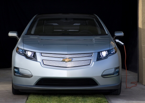 .
.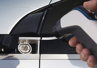
Shows Volt plugged in (Jan 2009)
Car male plug is on driver side just in front of the
rear view mirror
(Is this plug right? It looks like three pins,but
the standard SAE J1772 connector has 5 or 7 pins.)
GM Volt lithium
ion battery
123 Systems
in Watertown (spending 60 million on new factory) and a large Korean company
(LG Chem) are the two companies competing to provide the Lithium ion batteries
for the GM Volt. In Jan 2009 I read LG Chem has been chosen.
"A123 is still sort of a startup, they're still ramping up, and A123 has been specializing mostly in ...cylindrical cells, which are good with power tools and stuff. What we need here is prismatic, which is flat cells. And LG Chem is just farther along," GM's Lutz said. (Jan 09)July 9 09 Prototype battery reported to be 200, 3.6V cells. (no info on pack voltage). It's probably either 360 V with double paralleling, or 720 V all in series.
(update) A July 3, 2009 report has GM comitting to buy lithium ion batteries from Hitachi for 100,000 cars. However, they are apparently not for the Volt, they are for other GM hybrids. LG Chem is still being reported as the battery supplier for the Volt.
(update) Dec 2009 Michigan Gov with GM officials announced 336 million investment in a plant to make the Volt (Detroit's Hamtramck Assembly Plant).
(update) Jan 9, 2010 Michigan gov showed up at opening of GM's new lithium ion battery plant (for Volt) in Brownstown Township. 106 million of US taxpayer dollars to be invested in this one battery plant! Here is photo (shown with thermal shield) of first Volt battery pack from the plant.
Open and closed views of GM Volt battery pack
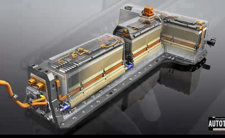
Visible stack up looks like 96 modules in series (345V
battery voltage)
Each module has three parallel 3.6V lithium ion cells
(288 cells total)
Peak power: 330 VDC x 330A = 100 kw (approx)
330A is probably carried by two orange wires (left)
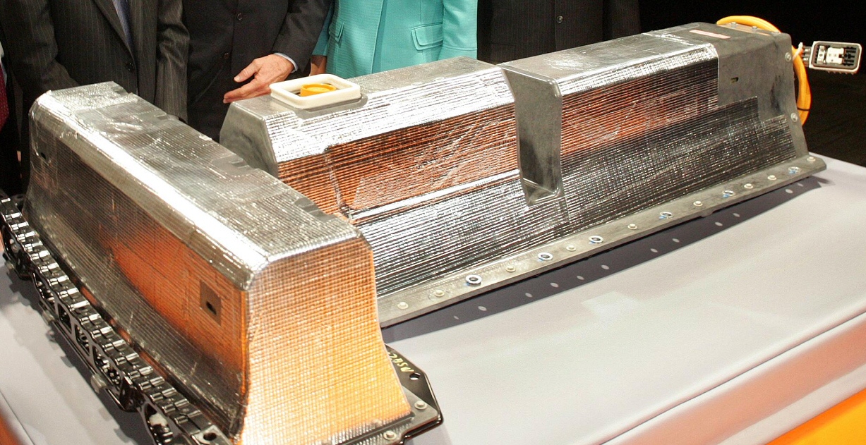
GM Volt lithium ion battery pack (from new Mich factory)
Jan 2010
(at right can be seen how the foil insulation is just
glued to case)

GM Volt production battery pack (without external
foil insulation)
Weight > 400 lbs
> 200 cells
16 kwh with 8 kwh usage
-- The Volts T-shaped battery packs are composed of >200 (Wikipedia says 220 cells) individual 3.6V lithium-ion cells, each of which is a thin sheet about the size of half a piece of paper and about as thick as a CD case. Total weight for the whole pack is about 400 lbs which, when taking into account structural modifications, adds 700 lbs. to the total vehicle weight.Derived Spec of LG Chem cell for GM Volt (see below for update based on GM battery video)
VAh
72.7 VAh/cell = 16,000 VAh/220 cells
Ah
20 Ah rating @ 3.6V cell = 72.7 VAh/cell/3.6 volt/cell
weight
826 gram/cell = (400 lb x 1 kg/2.2 lb)/ 220 cells
The largest lithium ion battery on the LG Chem site is their E, which is about half the GM Volt cell. This is an old spec (2004).
E1 Ah
10 Ah @ 3.6 V
Weight
245 grams
Dimension
20 cm x 9.4 cm x 0.7 cm
ESR ?
3 mohm = AC impedance @ 1 khz
Max continuous discharge 30 A
(P/cell @ 30A = 30^2 x 3 mohm = 2.7 watts)
"short circuit test Z"
50 mohm (I pk = 3.6V/ (50 + 3) mohm = 68 A)
----------------------------------------------------------------------------------------------------------
MIT Technology review 27 min video of GM Battery Plant
tour (6/2009)
Some of the
best GM Volt battery info I garnered from a long (27 min) video taken by
MIT's Technology Review magazine energy editor (Keven Bullis) during a
tour June 2009 of GM battery plant. The most interesting speaker, Bill
Wallace, Engineering Group Manager), Rechargeable Energy Storage, starts
19:12 into video. (Wallace identifies himself as the engineering group
manager for the Volt battery.)
http://www.technologyreview.com/video/?vid=369?channel=business

GM Volt production Li-ion prismatic cell
(screen capture from MIT Technology Reivew GM battery
tour video, 6/2009)
--- 150 W-hr/kg
(for GM volt battery) answer to question. This is probably a battery cell
spec and implies 16 kwh/0.15kwh = 107 kg (235 lbs).
-- engineering
manager speaking
-- battery is at production stage, 5th iteration of car battery pack
design
(100 packs built at time of video, 300 packs to be built by Q3 2009)
-- Volt battery pack is 1/3rd volume and 1/3rd the mass of EV1 battery
pack
(EV1 lead acid battery version had roughly same Kwh and peak power spec
as Volt)

Ev1(left) vs GM Volt (right) battery pack
(GM Volt 16 Kwh, EV1 lead acid 16 to 18 Kwh)
-- 16 khw total "usable energy"
-- 110 kw "peak power"
-- 400 lbs
-- enclosure is fully sealed against water ? dust (since it's under car)
-- 155 different components inside the battery pack
-- notch in battery pack is for a car structural element to pass though.
The battery pack
itself includes some structural elements
-- "over 200" Li-ion cells
(he smiles -- why is the # of cells being hidden, which it clearly is?)
-- we cool and heat every cell in the pack
-- highly insulated, which is key to maintain the batteries' temperature,
"temperature kills batteries"
Questions (to Wallace)
-- Is battery thermal management done with liquid or air? answer liquid
-- What is # of cells. ans, I can't give you an exact number but it's between
200 and 300
when pressed he said closer to 300, but less then 300
-- What temperature are you maintaining inside. "ideal temp for Li-Ion
is
room temperature, 25C. Inside temperature is held appox between
10C (50F) and 35C (95F).
-- So what's the thermal strategy, say when you are parked? How much energy
will you draw
when parked? Tesla had a problem drawing energy to run a fan when parked.
Ans,
basically we're working on it. We have the capability to heat or cool battery
in
any mode, even if car is just sitting. Passive insulation is very important.
Once you shut down car you need to be able to maintain (battery) temperature
without using energy. To do this we use a "very expensive" insulation
package.
Summary of video GM Volt battery info (6/2009)
Khw
16 Kwh ("usable")
Peak power
110 Kw
# of cells
275 cells +/- 25 cells ("200 to 300, but closer to 300")
288 prismatic cells (10/11/10 spec update)
Battery voltage (oc)
346V (est) based on 288 cells @ 3.6V wired (1/3/11 update)
3 in parallel x 96 in series (based on 2008 article in Pop Sci
on battery pack that showed battery was 300 cells wired 3 in
parallel and x100 in series)
Cell Ah (est)
16 Ah @ 3.6 V = 16,000 Whr/275 cells
Est cell pk current
110,000 watt/990V = 111 A
Cell ESR (est)
? [0.33 (Toyota) x 3.6V/ 111A = 11 mohm]
(scaling from LG Chem spec 3 mohm/1.6 = 2 mohm approx)
Cell weight (est)
384 grams = 16 Ah x 3.6V/150 Wh/kg
Pack cell weight
106 Kg (233 lb) = 384 gram/cell x 275 cells
Pack weight
"400 lbs" (unclear if this includes structure, but it seems to)
Thermal
10C to 35C (50F to 95F) operating cell temperature
(uses expensive passive insulation and liquid thermal
heating/cooling system, system is sealed for dust)
Note these numbers hang together well. Each cell looks like it has about x1.6 the capacity of the 2004 LG Chem cell (above), and this agrees with the picture. And for first time real info on the battery pack thermal heating/cooling system and a 10% accurate estimate of number of cells. These Li-ion Khw cell numbers look excellent about x3 higher than NiMH cells by weight.
The Prius NiMH cells are packaged in handleable plastic cases and stacked up. In Volt the photo shows each cell looks like a (delicate) foil with protection provided by a sealed outer structure. In Prius it looks like a bad cell could be popped out and replaced, but not in the GM pack, which is sealed.
Peak voltage sag (10/15/10)
In my GM-Volt
block diagram I show the peak power from the batteries could possibly be
165 kw if both the 111 kw main motors and the 54 kw mot/gen are
run to their limits. My guess is the 288 cells are arranged as 96 stacks
of three in parallel forming a 350 VDC bus. The peak cell current then
would be about [1/3 x 165,000/350V = 157 A] @ 165 kw.
Taking the 2 mohm cell impedance estimate above the voltage droop of the bus would be [96 x .002 ohm x 157 A = 30 V] @ 165 kw. This is only a modest 8.5% drop and would have little effect on performance. On the other hand if cell impedance is at the high end of the estimate (11 mohm), or 5.5 times higher than 2 mohm, then the bus sag is something like [5.5 X 30 V = 165 V] (or more), which brings the bus below 200 V and would be intolerable. Conclusion: unless there is a voltage regulator in the GM Volt architecture, then the cell impedance has got to near the low end of the estimated range in the 2 to 4 mohm range
Summary of GM video thermal info
The battery cells are seal into a very well insulated liquid heat/cool
structure that will hold the temperature inside between 50F and 95F. Expensive
passive insulation has been used to minimize the battery drain when parked
in cold or hot weather for temperature control. (No hint as to the energy
required for cooling when driving in hot weather. There appear to be no
fins on the package that might aid cooling by using the air flow under
the car.)
Assuming 1.9 mohm/cell (scaled from 3 mohm LG Chem spec for 16 Ah cell) @ 110 kw
volt drop/cell = 110,000 w/(275 cell x 3.6V/cell) x 1.9 mohm
= 111A x 0.0019 ohm
= 0.21 V (@ 110 Kw peak power)
(minimal sag at peak power 3.6V => 3.4V)
watt dissipated/cell = 0.21 V x 111A
= 23 watt (@ 110 Kw peak power)
watt dissipated/pack = 275 cell x 23w/cell
= 6.4 kw (@ 110 Kw peak power)
efficiency = 110 kw - 6.4 kw/110 kw
= 94% (@ 110 Kw peak power)
ESR losses go as current^2 (power^2), so averaged over driving conditions losses will far lower than the peak power shown above.
The small voltage
sag of the large Li-ion battery pack, even at peak power, means that unlike
the much smaller battery packs used in hybrids, there is no need to regulate
the battery voltage, the battery can be applied directly to the motor inverter.
My guess is that they are paralleling x3, resulting in a nominal 330 VDC
battery voltage used as the bus for a 600 V, 600A IGBT inverter.
Peak transistor current would be 3 x 111A = 333 A.. The 8 X4 inch Infineon
six pack shown (far above) would mate nicely with a x3 paralleled version
of this battery pack. (EV1variants had battery voltage 312V to 343V).
----------------------------------------------------------------------------------------------
Volt battery pack weight estimate
GM volt specs
on the car battery pack are 16 Kwh. This is more than an order of magnitude
higher than Prius, about x12 = 16 kwh/1.31 kwh times higher. Have not seen
a weight spec the Volt battery pack on it, but we can estimate it. If the
lithium ion cell has x2 the energy density of NiMH, then the lithium ion
cells would weigh 64 lbs (Prius) x 12/2 = 384 lbs. If the energy storage
density of lithium ion over NiMH is closer to 1.5, then the weight rises
to 512 lbs. Add in 50 to 100 lbs of structure and I get a weight range
for the battery pack of 450 to 600 lbs.
(update, July 9, 09)
Prototype battery pack weight reported to be 400 lbs, 700 lbs with
structure Wikipedia says 375 lbs.
(update 3/10)
In an article in the New Yorker on lithium by a guy who toured the GM battery
plant it says the amount of the element lithium in the 400lb Volt lithium
ion battery pack is only 4 lbs.
Peak current requirement for lithium ion cells
The large
battery pack ( x12 more kwh's than Prius) planned for the Volt eases the
peak current/power demands on the lithium ion cells. I have seen nothing
on the Volt battery pack voltage or structure, but it seems to me there
must be a lot of paralleling. For example, x12 energy storage could be
x2 higher energy density of lithium ion over NiMH with the other factor
of x6 coming from paralleling of cells. With x6 paralleling then 150 hp
(x3 Prius) electrical could be achieved with each cell putting out half
the peak current of NiMH cells. This is in fact consistent with the only
spec of a high power lithium cell (from 123 systems) I have found.
Volt plug-in recharge time
GM marketing
writes the plug-in full recharge time will be 3 hr from 230 VAC and 6hr
@ 115V. Well as a power engineer I decided to check it because it didn't
smell right, and sure enough it's (probably) not right.
115 VAC line power limitation
Note GM is
claiming the plug-in time using a typical residential 115 VAC line is twice
the time it takes when the battery pack is recharged from a higher voltage
(higher power) 230 VAC line. The typical 115 VAC line is brought up to
it maximum 15A current with a 1,500 watt room heater. The small wire and
fuses in 115 VAC lines limit them to delivery of 1.5kw of power.
In six hours a 115 VAC line can only deliver 9Kwh (= 6 hr x 1.5kw). This is a long way from the speced 16Kwh rating. Sure enough when I poked around the LG Chem site, they say the Volt battery pack recharge time, and as manufacturer's of the battery they should know, is 3 hr at 230 VAC and 8 to 9 hrat 115V. I posted this discovery in a comment to NYT article on the Volt. (Recharge time depends on the used capacity of the battery, reportedly it will charge to 80% upper and 30% lower, so 0.5 x 16 = 8kwh, consistent with 6 hr from 120 VAC line. )
NYT driving a Volt prototype (in generator mode)
She asks the
question will the car be a slug in generator mode and then never answers
the question. Car uses specially designed 'low rolling resistance' tires.
A good question is, What is the engine's speed at rated power and peak
power. The reviewer found the car's engine/generator cycling disconcertingly
from a (barely audiable) low speed to a loud, disconcerting 3,000 or so
RPM.
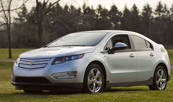 .
. 
GM Volt with five pin plug (NYT 11/09)
By LINDSAY BROOKE, November 19, 2009
SITTING behind the wheel of a 2011 Chevrolet Volt prototype on Wednesday, I found myself confronting what may be the greatest fear that future owners of electric vehicles will face: a battery-charge indicator showing just a few miles of remaining range. If I were out on a desolate Interstate in a vehicle powered solely by batteries, Id be praying to the god of electrons for a place to pull off and plug in a charging cord. But my drive is at General Motors proving grounds here, and Im about to experience what the Volts vehicle line director (and my passenger), Tony Posawatz, says is the cars trump card: a gasoline-powered generator under the hood.
Like other reporters, I had already driven Volt prototypes in the battery-powered mode, and they were predictably smooth and silent. But for eventual Volt owners, a crucial and so far unanswered question is how the car will perform when the batterys charge is depleted and all electricity is provided by an onboard generator, driven by a gasoline engine, that has no mechanical connection to the wheels.
Will it be a slug? How annoying will the noise of the generators engine be in an otherwise mute car?
G.M. engineers say that a fully charged Volt is capable of 40 miles of purely electric driving before the computer calls for the generator, which has an output of 53 kilowatts (about 71 horsepower), to start and sustain the batterys minimum charge level the extended range operating mode.
So what is life after 40 like in the Volt?
It takes a few laps of Milfords twisty, undulating 3.7-mile road course to deplete the remaining eight miles of battery charge. With the dashboard icon signaling my final mile of range, I point the Volt toward a hill and wait for the sound and feel of the generator engines four pistons to chime in.
But I completely miss it; the engines initial engagement is inaudible and seamless. Im impressed. G.M. had not previously made test drives of the Volt in its extended-range mode available to reporters, but I can see that in this development car, at least, the engineers got it right.
I push the accelerator and the engine sound does not change; the gas pedal controls only the flow of battery power to the electric drive motor. The pedal has no connection to the generator, which is programmed to run at constant, preset speeds. This characteristic will take some getting used to by a public accustomed to vroom-vroom feedback.
A few hundred yards later, as we snake through the tracks infield section, the engine r.p.m. rises sharply. The accompanying mechanical roar reminds me of a missed shift in a manual-transmission car. For a moment the sound is disconcerting; without a tachometer, I guess that it peaked around 3,000 r.p.m.
I asked what was going on. The system sensed that its dipped below its state of charge and is trying to recover quickly, Mr. Posawatz said. The charge-sustaining mode is clearly not where we want it to be yet.
Immediately the engine sound disappeared, although it was still spinning the generator. A few times later in our test, the generator behaved in similar fashion too loud and too unruly for production but there is time for the programmers to find solutions. Volt engineers are revising the cars control software, which will have the effect of feathering the transition from the nearly silent all-electric mode to the charge-sustaining mode, when the generator will be operating.
Were designing a software set of rules, which will just require more seat time for the engineers to finish, Mr. Posawatz said. We have nine months to work this out. The sound of the generator running at steady highway speeds is something Volt owners, and others who appreciate the flexibility and efficiency of this type of hybrid system, may have to accept.
Unlike many electrics, including the Tesla Roadster, the Volts electric drive has no whine. The car feels solid and planted on the road. Clicking the Sport button on the dashboard releases a bit more oomph than when in Normal mode; in terms of efficiency, there isnt much difference between the two except at peak power.
The Low mode Chevrolet plans a flashier name for it by next fall is unique in the electric-car world, and a useful feature. While coasting, it applies electric motor braking, then smoothly blends in the regular brakes.
Even beyond the regenerative function, Low mode offers one-pedal driving in slow speed, stop-and-go, and downhill environments. The regenerative braking, whether applied through the Volts foot pedal or by pulling the shift lever down into Low mode, is both progressive and predictable. This is in stark contrast to the harsh, abrupt regenerative braking delivered by BMWs all-electric Mini-E, for example.
There is minimal body lean in the tight corners. The low-rolling-resistance Goodyear tires created specifically for the Volt provide excellent grip. Throughout my test, the prototype behaves admirably. At its current state of development, the Volt is an extremely refined vehicle.
High speed torque problem? (Sept 2010 update)
There are
recent hints (June 27, 2010) that the high speed torque (high speed acceleration)
in the GM Volt my be poor and that GM might be planning to radically alter
the architecture of the car to fix it! These hints come from an article
about the European version of the Volt, the Opel Ampera, which is to be
built in the same Michigan factory as the Volt, but goes on sale a year
later (end of 2011). This story was on the GM-Volt site (not connected
with GM). Here's the link:
The story is that testing of the Volt and Ampera by journalists has been restricted to 50 mph top by a twisty, cone strewn test track they have been allowed to drive on, but that a European journalist got to drive the Ampera on city streets. He reports it accelerates badly above 50 mph. But here's the kicker:
General Motors is working on the problem and this autumn plans to unveil a mechanical direct-drive from the engine to the front wheels through the existing twin-clutch planetary gearbox. This would reduce the energy losses of turning petrol power into electricity to drive the car at high speeds, and would also give the Ampera more spritely overtaking performance.Is Volt really a hybrid?
Translation: They are converting their electric car into hybrid? It could be effective. There are 90 hp available from the engine, so why not let the electric motor max out during accelertion using only battery power and add in some (or all) of the 90 hp from the engine mechanically. After all hybrids do work well, and what they have here, they may be thinking, is a hybrid with a big battery.
But something about this story smells a little. The planetary gear box is the heart of a Toyota like hybrid. How come there happens to be a planetary gear box 'handy' in the Volt/Ampera that they can just tap into. An electric car would be expected to have no gearbox. (Tesla started off with a two speed gear box, partly because the boss thought customers driving a high performance car would like to shift, but took it out when it kept failing.)Hybrid transmission in Volt? (Sept 2010)
The poster's technical case (Feb 2010) is in link below. This is full of good info including even GM patent on the transmission. He argues that cars with no transmission end up needing motor with very wide speed ranges like 0 - 13,000 rpm, which is what he calculates for EV1 at its top speed of 80 mph. And I see in Tesla and other electric cars. However with the dual mode transmission (below) the two smaller 55kw motors combined together with different gear ratios can be designed to operate over a much smaller speed range (7,500 rpm max) so better efficiency and probably more reliable. I like it, but now in an 'electric' car we a complicated gear box of a hybrid, because basically it is a hybrid, just a hybrid with a big battery and an extended all electric mode. If true, it shows how truly deceptive GM has become! (It also would mean the Volt uses PM motors not induction as earlier reported.)
http://gm-volt.com/forum/showthread.php?t=4181
He points at this UC Davis 2007 paper as background:
http://steps.ucdavis.edu/People/bdjungers/presentations/UCDavis_Spring2007_TechReport.pdf
![]()
Transmission for planned GM Saturn SUV 'Dual Mode'
hybrid
Note the 'motor' is really two 55 kw PM motors ,
which can be operated separately or lashed together
to make a 110 kw motor
(screen capture from link below)
http://www.che.ncsu.edu/ILEET/phevs/plug-in_2008/1A-1_GM%202-ModePHEV%20VUE.pdf
GM Volt revealed
to be a hybrid! (10/10/10)
Finally GM
comes clean and reveals details of the architecture of the GM Volt. And
it is not the simple structure that GM marketing has been saying (or implying)
it is [engine => generator => battery => inverter/motor => wheels]. It
includes all of this simple structure and below 70 mph this is how the
car works. But above 70 mph the 111 kw (main) motor does not have the torque/speed
needed for good acceleration and 100 mph max speed.
(update 8/22/11) GM marketing continues to obscure the true nature of this car, meaning that it is not a hybrid. For example, in a technology video currently on the Volt website a GM manager says, "The Volt uses electricity all the time to run the car." He continues, "It has a an electric motor with 111 kw of peak power and that is always what drives the car". Well, maybe not outright lies, but certainly deceptive.So for operation above 70 mph GM has added to the architecture a planetary gear set (like Prius) and three clutches. This added path provides a mechanical path for some of the engine power to get to the wheels. So above 70 mph, the GM Volt is basically a hybrid with a big battery; but unlike the standard hybrid here the electrical path is dominant and the mechanical path provides supplementary power as well as a continuous variable transmission. The planetary gears act as a 'power combiner' (where in the Prius the planetary gears act more as a 'power splitter') combining the power from the main (111 kw) motor and the generator (55 kw) run backwards as a motor, or if the battery is depleted, mechanical power from the engine run through the continuous shaft of the generator.
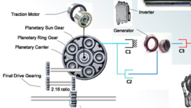
GM Volt power train showing plantary gears and three
clutches (10/10/10)
Two blue/green clutches freeze the ring gear or connect
it to the 54 kw motor/gen,
red clutch connects/disconnects the 54 kw mot/gen
to the engine
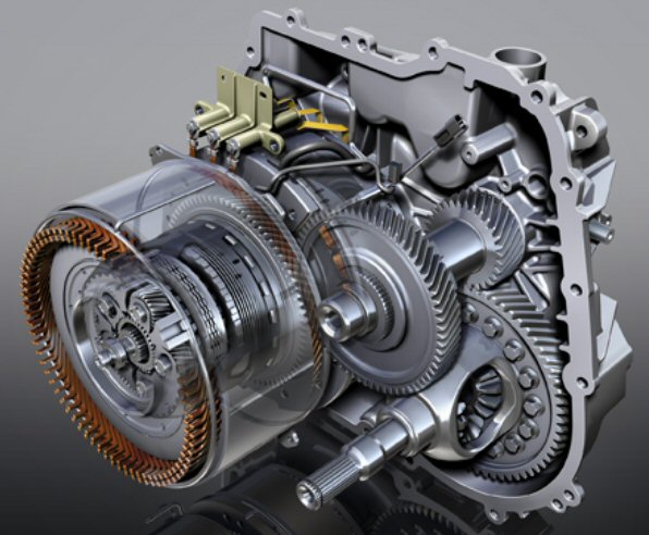
cutaway of GM Volt power train
My GM Volt architecture sketch (10/15/10)
Here's a sketch
I made hi-liting (in blue) the extra components of the Volt drive train
that GM has hidden for nearly two years. Independent testers report the
car has good acceleration and performance over the whole speed range both
in all electric mode and with a depleted battery, but the downside is the
cost of adding a complex hybrid type planetary gear set and three
clutches. (Details of the architecture are pulled from a patent filed 2007
by GM which is believed to be the architecture of the Volt.) The GM spec
has finally disclosed that the battery consists of 288 cells. Here I am
guessing
that the 288 cells are arranged as 96 stacks of three parallel cells (96
x 3 = 288), because if the lithium cells are 3.6 V or so (exact voltage
not disclosed), then the bus voltage comes out about right (350 VDC) for
600 V IGBT's in the inverter.
(best guess) GM Volt architecture
parts in blue (planetary gear set and three clutches)
were hidden by GM until Oct 2010
Acceleration boost below 70 mph? (10/15/10)
(1/4/10 update)
My figuring below that torque is added from the gen/engine path during
hard acceleration is probably right.. In a YouTube test drive by an automotive
type he says when you step hard on the gas (he is doing 40 mph or so on
a country road) you can feel a "kickdown" bringing in extra power. My sketch
shows it doesn't matter if the extra torque comes from the generator/battery
or engine, in either case the clutches have got to throw and the planetary
gears go into action to add in the 2nd torque.
--------------------
This has not
been disclosed by GM, but looking at this architecture I find it hard to
believe that GM is not using the 54 kw motor/generator to boost acceleration
of the car (even from a dead stop). Essentially all the parts are in place
to boost both the torque and hp of the car in all electric mode by as much
as 50% (!) utilizing the 54 kw generator as a motor and combining torques
through the planetary gear set.
However, I can think of one reason why a strong boost via the lower path may not be desirable. With 50% more torque and hp the car in all electric mode would (perversely) have performance that is 'too good'. The engine does not (appear to) have the sustained power capacity the battery has, so in some driving scenarios a noticeable loss of car performance might occur with a depleted battery. I was struck that reviewers noted that the car performed about the same in all electric mode and with battery depleted, so my guess is that this was a design goal, and it's obvious that marketing would like it, because it keeps things simple.
There is a complete description of the GM Volt drive train in Motor Trend magazine and their test drivers got to drive the car for 100 miles in the field. he GM Volt is now revealed to be a hybrid with a three axis planetary gear set like the Prius. Quote: "Markus liked driving the car and he noted he was surprised about the direct mechnical connection."
http://gm-volt.com/2010/10/11/motor-trend-explains-the-volts-powertrain/
Details of the powertrain here:
http://gm-volt.com/2010/10/12/chevrolet-volt-electric-drive-propulsion-system-unveiled
There's even a figure in the article comparing the two planetary gears. The Volt has the engine, wheels and generator hooked connected to different gears than the Prius. There's info about how this functions in the GM patent application (see below).
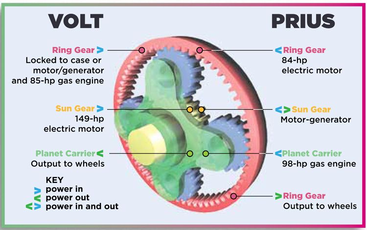
Motor Trend article on GM Volt geartrain (Oct 2010)
The article says at 70 mile/hour the electric motor maxes out in speed. Above 70 miles per hour in all electric mode, the wheels are powered both by the electric motor and the generator (run as a motor). The article is not crystal clear, but it appears that the gas engine remains off, so the apparently the link from generator to battery must be an inverter (not a rectifier). So above 70 mph in all electric mode the battery runs the wheels through two motors (2nd motor being the generator), their torques combined in the planetary gear set. The generator has a hp rating of 72 hp (vs 150 hp for the electic motor), so together at high speed they boost available hp to 222 hp, or about 150% of the motor alone.
The article description with gas engine on (battery in charge sustain mode) above 70 mph is again a little unclear, but I think this is what is going on. At all speeds includein above 70 mph with depleted battery the engine powers the generator which (coupled to the battery for peak boosts) powers the main motor (150 hp motor). However, it it worked this way above 70 mph the car would be a pig. The generator can't now be used to provide wheel torque as a motor since it is acting as a generator powing the main motor, so in this mode the torque from the engine now couples through the planetary gears directly (mechanically) to the wheels. It is a hybrid, in this mode the wheel are driven by a combination of electric and mechanical torque. GM is quoted as saying: 'The gas engine participates in the motive force' and 'the engine never drives the wheels all by itself', which is correct.
Motor Trend says the performance of the car is good in all modes. It accelerates faster than the Prius (0 to 60 in 8.8 sec (electric), 8.7 sec extended, vs 9.8 sec for Prius.
My comment -- just a hybid with a big battery (10/10/10)
The GM Volt
appears to have a sophisticated architecture with good performance. Good.
Not so good, however, is it is not all that radical. It's now coming out (well hidden for years, Why?, Probably because it killed the sex appear) that it's basically just a hybid car with a big battery!! And no wonder it's expensive it has all the planetary gear overhead of hybrid plus higher capacity electronics and a 10k 400 lb battery.
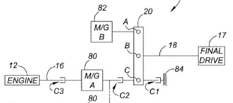
Here's what looks like the GM-volt architecture (from
2007 GM patent)
www.freepatentsonline.com/20090082171.pdf
(20090082171, Mar 26, 2009)
A,B,C is planetary gear set
A (sun gear), B (planetary carrier), C (ring
gear)
M/G (motor/generator) B is 111 kw main motor
M/G (motor/generator) A is 54 kw main motor
engine power rating: 66 kw/ (89 hp)
-- Key here (I think) is that the engine shaft goes right through the 54 kw generator, so >70 mph with battery depleted the 66kw engine can both power the generator (to power the main motor) and still have some excess torque left over that is coupled mechanically into the planetary get set to the wheels.
-- Two motor mode (> 70 mph), the torques or the two motors are combined for delivery to the Final Drive (wheels), or alternatively, the speed of M/G A determines the gear ratio from M/G B to the Final Drive. This is the Electrically Variable Transmission (EVT).
-- Article commentary on patent says, "GM seems to have stated that the Volt never mechanically couples the Engine to the wheels.", which the patent clearly shows is possible. (If they did say this, and I bet they did, and we now see this is a (marketing) lie. Everyone in forum commentary remembers GM saying the engine would 'never' directly drive the wheels.
Toyota
Prius plug-in hybrid 2012 (Aug 2011)
Toyota has
announced what they call a plug-in hybrid for sale in early in 2012. By
putting a 300 lb, 5 kwh (approx) battery in a Prius they have a direct
competitor to the Volt. It's as an electric car for 13 miles, and then
runs on its engine as a hybrid (probably like a standard Prius). They are
going to start selling in in the north too (Mass, Vermont, NH, Washington).
A web site is up with some info, but full specs won't be revealed until
Sept auto show.
I think going with a battery 1/3rd the size of the Volt (16 kwh) makes a lot of sense. Instead of an extra 10k for battery it's 3.3k and much of this will be paid for by government subsidies for electric cars. Instead of 1,000 lbs it's 300 lbs and a lot smaller too. Some odd things (not yet sorted out). Read max speed in electric mode is 62 mph, which means its only for city. You can prevent it from going into electric mode, allowing you to drive highway on engine and switch to electric in city. This makes sense and I read Volt will have this too (in Europe). For some reason I don't understand instead of just making the hybrid battery bigger, then have added another battery (maybe even in two segments) for electric mode that is line charged. I can see lots of production reasons why this makes sense, but not sure if functionally it makes sense.
(Oct 2011) Saw Toyota plug-in hybrid (writtten all over the side) on road in Cambridge today. It was marked as a ZipCar, which is apparently cooperating in its testing. Yup, I read in Jan 2011 ZipCar got 8 cars to test for use in three cities and Cambridge MA is one of them.
Battery
5.2 kwh, 288 cells, 3 modules
Battery thermal
three cooling fans
Battery weight
350 lb
Charge time
3 hr @ 120 VAC
Motor
60 kw (80 hp)
Fuel tank
11.9 gal
Motor at 60 kw is not large enough to provide the 120-130 kw needed for a fast acceleration, so the engine starts during hard acceleration to provide the additional 60 kw. Engine also turns on when heater or air conditioner is powered on. (The article reads like the car still runs electric on the battery, with the engine only providing electric power to run the heater and air conditioner.)
quasi-electric
Fisker Karma sedan
(update 5/1/2013)
Fisker
Karma is (essentially) BANKRUPT. Most of its employees (600 at one point)
were laid off in April 2013. Gone is its 1.4 billion in capital. This car
will probably become a collectors items since only about 2,200 were ever
made. One story reports 338 (confirmed) were destroyed when submerged on
NJ docks by hurricane Sandy, 600 remain unsold on dealers lots, dealers
invoice price was 70k.
Besides Fisker's and Quantum's engineering conservatism running the electric motors too slowly making the car too heavy (over 5,000 lbs), they had bad luck with their battery supplier (A123 Systems) going bankrupt and 338 of their cars, about 15% of their total production, destroyed in one shot submerged on NJ docks.
Well documented history of Fisker Karma is here:
Classic
video --- Karma has the world's worst screen car controller (update
7/26/13)
Even though
Fisker Karma is long gone, I just stumbled upon three videos on the car
by Brian Greenstone, who is a Fisker Karma owner. These are the best car
video reviews I have ever seen, long, smooth, knowledgeable, just fantastic.
The one below is a classic and should survive the car. The Fisker like other high end cars has almost no knobs, every adjustment (climate, radio, phone, navigation, etc) has to be handled through a touch screen display. In the May 2012 video below Greenstone, who is an expert here as he is an award winning software and interface designer, goes over the Fisker software in detail (six month after the car has been in production and after a major software upgrade). This controller has got to be the worst car screen controller ever put into production, hands down, no contest. It is such a piece of complete shit it takes him 41 minutes to go through it and hilite some of the problems, and every point I agree with. And more important these absurd screen car controller are dangerous, because they are hugely distracting while driving, and the poorer the design, the more dangerous.
http://www.youtube.com/watch?v=rK8MqjagHu8&list=PL661CBDC640E30A6A
This controller has every kind of error, from idiot low contrast screen, tiny fonts, no audio feedback on keypresses, useless screens, functions that don't work, bad layout, inconsistent use of highlighting and arrow direction, unneccessary keypresses, absurdly nested menus, and simple keypress misses can cause near disaster while driving on highway as your mirrors can fold in (with of course no easy way to recover). A complete piece of crap, and the navigation system is also fundamentally flawed and complete junk. Nice going Fisker, no wonder you went bankrupt.
(update 11/4/12)
It's not known
exactly what happened, but 15 or 16 Fisker Karmas (1.5 million dollars
worth!) on the dock in NJ went up in flames. The presumption is they got
wet with salt water. Fisker has a new CEO, the previous one lasted just
five months. A123 Systems, who is Fisker's only battery supplier, has filed
for bankruptcy. Consumer Reports bought a Fisker Karma at a dealership,
paying 107k, the most they every paid for a car. The car ran 180 miles
and crapped out, totally dead, and was towed back to the dealership.

More than a dozen Fisker Karma roadsters soaked with
salt water by hurricane in NJ go up in flames
(source --- http://updates.jalopnik.com/post/34669789863/more-than-a-dozen-fisker-karma-hybrids-caught-fire-and)
Prototype into production(update 2/10/12)
As an engineer, Fisker's many woes are not all that surprising. A car is an extremely complicated engineering device, and it must be manufactured in volume for a company to be viable. The difficulty of starting a car company and assembling from scratch an engineering team to do the job is daunting. Even if enough good engineers could be found (doubtful), they have no institutional knowledge of devices, suppliers, etc to fall back on, and of course the likelihood that management would provide them with sufficient time and money to design a car and wring out problems is remote. What it looks like has happened at Fisker, not surprisingly, is that in effect they have taken an engineering prototype and put it into production. Hence all the problems, like the car dying at Consumer Reports.Not that this hasn't happened before. I remember reading in the history of the V2 rocket that that's what happened there. The engineering team under Wernher von Braun at Peenemunde had designed what they considered to be an engineering prototype (it needed all kinds of tweaks and adjustments to work), but Hitler forced it into production.
"More perceptive reviewers find the car overweight, inefficient, and capable of only mediocre performance (maybe because it has a 2,500 lb drive train!) that falls well short of its eco-friendly goals." (whatever the hell that means)Car and Drives says they found the electric range to only be 24 to 28 miles. Fisker claims 50 miles.
(update 2/9/12)
According
to the WSJ today the US Energy dept froze further funding to Karma for
their follow-on sedan (Nina), since they have missed targets that are part
of the 529 million dollar US Energy Dept loan agreement. This was the car
planned for production in the old GM factory in Delaware. WSJ says the
have accessed 193 million of the 529 million before freeze. With further
taxpayer funding frozen Fisker laid off about 26 people working on the
sedan at the Delaware plant and 40 in Calif.
A123 Systems
Also today
Kevin Bullis of MIT's Technology Review has an article online saying Fisker
is a "key customer" for A123 and their recent troubles are bad news for
A123. I think A123 System, MA manuf of lithium ion batteries, has made
a major mistake in hitching its wagon to Fisker Karma, and its overweight
5,200 lbs 'sub-compact' turkey of a car. That's right its first (and only?)
5,200 quasi-electric car has been ruled a sub-compact by EPA due
to its tiny interior volume (all those batteries and the back seat is smaller
than a Honda Fit).
Bullis says maybe 30% of its revenue 2011 and 2012 was expected to be from sales to Fisker Karma, but Fisker has "unexpectedly" canceled battery orders. (Could it be their overweight baby is not selling?) Bullis says Karma has nowmanufactured 1,500 cars and sold hundreds. A123 Systems has built a battery plant to supply Karma and now it has idle capacity. A123 also has a US dept of energy loan (249 million) and for 2011 they are operating at a big loss. Bullis is hinting that if Fisker gets into a lot of trouble, it could drag A123 into bankruptcy, though if they survive 2012 they have a lot of other customers whose orders they expect to grow.
(12/31/11) Well, Fisker got to production (in Finland). In headlines today they are recalling all their cars. Loose coolant clamp could lead to spill into battery compartment which could cause a short (they say). (Good engineering.....)
"Fisker Automotive is recalling all 239 of its 2012 Karma luxury plug-in hybrid cars of which 50 are in hands of consumers. Prices on the 2012 model start at $103,000."Drudge headlines they got 529 million dollar US loan to build cars in Finland. In 2009 when they get loan plan is to build cars in old GM plant in Del. Picture shows Biden sitting behind Fisker Karma at press conference. But later they announce:
"There is no contract manufacturer in the U.S. that could actually produce our vehicle," the car company's founder and namesake told ABC News. "They don't exist here." Really, they couldn't find a contracting company in US prepared to build a complete car. What a surprise the must have been!
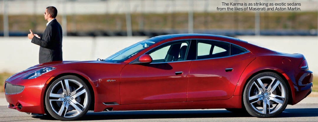
2012 Fisker Karma production model
(update 11/6/11) EPA has rated the electric range of the 22.6 kwh Fisker Karma at 32 miles vs 35 miles for the electric range of the Volt with its 16 kwh battery.
(update 8/2011) Fisker Karma is still alive, now branded
as a 2012. You actually find a list of retailers and when I checked a
Norwood Ma Jaguar dealer on the list, the dealer site
says he will soon be selling the Fisker Karma.
(update 11/2010)
True electric extended range car
Fisker put out a
press release that theirs is the only true extended range electric
car, which means they are saying that unlike the Volt their engine will
not be mechanically coupled to the wheels. This is confirmed in articles
as production starts. The engine only runs a generator, it is not mechanically
coupled to the wheels as in the Volt.
What Karma doesn't point out is that this super expensive car as a true electric has only moderate performance. If you want your nearly 100k car to give you sport car performance, the engine needs to run. To shave 2 sec off 0 to 60 mph and to increase top speed from 95 mph to 125 mph the you need to (about) double the power to the electric motors using the current from engine/generator (175 kw) added to the 150 kw available from the battery.
When you think about this, it is rather pecular. They have a 20 kwh battery (from A123), and they can't get 300 kw (100A @ 300V say) peak (or sustained) from it? (Nope, see below). Either they didn't with 100A wiring between cells or else the cells can't take the heat of 100A sustained. Maybe with the engine/generator sitting there the temptation was why bother, just run the engine, and keep the battery cool. Problem is this is supposed to be an electric car, and it costs over 100,000!
Whoops-------------------------------
Lost a factor of 10! This car requires a lot of power to drive its two 200 hp motors driving it. 300 kw is 1,000A at 300V. So the choice was getting 500A vs 1,000A from the battery. Now the decision to split it up with 500A from battery and 500A from generator makes more sense. Power goes as current squared, so using the generator for half the motor current cuts battery I^2R losses by a factor of 4. However, this just goes to show the problem in building a high power electric car.
Basically the Karma is a scaled up GM Volt, much larger, much heavier, much higher performance, and much more expensive. The car is a big (124 in wheelbase) expensive (88k), 4 seater sporty looking sedan that's functionally like the GM Volt. It's a plug-in hybrid with a large lithium ion battery pack for moderate electric range and an onboard engine to provide extended range.
electric range (EPA city)
50 miles
0 to 60 mph
5.9 sec (gas/electic mode)
7.9 sec (electric mode)
top speed
125 mph
engine
2 .0L, 4 cyl, turbo charged, 260 hp (192 kw) (2.2 L original)
(Ecotec engine made by GM)
gas tank capacity
9.0 gal premium (extra 250 miles @ 28 miles/gal)
two 200 hp motors
300 kw = 2 x 150 kw (400 hp total)
(981 ft-lb torque) (1,324 nm) (300 kw corner @ 2,164 rpm)
motors made in China (says Car and Driver)
motor location
PM motors in rear wheels, liquid cooled
generator
175 kw (236 hp) (about 150 hp are needed for wind at 125 mph)
inverters
three (two for motors, one for gen or charging?)
battery energy
20.1 kwh (from A123 systems) (315 cells) (22.5 kwh original)
(vs 16 kwh for GM Volt) Battery run to 15% capacity
"Nanophosphate technology" Googling this brings up A123 Systems
battery weight
606 lbs (light!)
battery size (in tunnel)
8.1 in w x 14.2 h x 6.14 ft
battery power
160 kw (216 hp) (181 kw says another source)
(Leaf pulls 90kw from their 24 kwh battery)
battery (open circuit)
336V
charge time
6 hr @ 240 VAC, 15A
wheelbase
124 in
weight
5,300 lbs (Karma spec) Yikes!
Beyond 50 mph the car operates as a "normal hybrid vehicle". Car has two modes of operation: stealth mode (all electric mode, 7.5 sec 0 to 60, 95 mph max) and sports mode (electric and engine power, 5.8 sec 0 to 60, 125 mph max). (The two switchable modes makes sense to me, it fits the technology.) There is no transmission. Fisker engineer confirms that the max battery power (200 kw) is not high enough to fully load the motors. Battery power alone is enough to do 7.5 sec 0 to 60 mph, but faster (to meet the 5.8 sec spec) engine power is added to battery power to provide the 300 kw for the motors. Engine is turbo charged to get high hp for given weight, fuel efficiency is secondary. One poster says EPA city favors electric vehicles, in real world driving at higher speed, so says electric range will not be 50 miles but more like 30 miles.
check
wind resistance
27 hp (20 kw) @ 70 mph
battery power
24 kw = 20 kw x 1.20 efficiency + tires
use 1/2 x 22.6 kwh
11.3 kwh = 24 kw x 0.47 hr (28.2 min)
distance @ 70 mph
32.9 miles = 28.2 min x 1.167 m/min
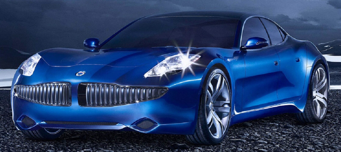
88k (now 95k) Fisker Karma quasi-electric (prototype)
shown at Detroit Auto Show winter 2009
(124 in wheelbase, 4.650 lbs, huge 22 inch wheels)
One reviewer calls the GM supplied engine "rude, crude, rough and lewd" at light load and the engine racket is much worse at full throttle! Maybe 260 hp from a 2.0L 4 cycle engine is a lot. It's unclear why this car weighs so much. The wheel base is large, but the frame is aluuminum. One review said Fisker wouldn't release weight and he was guessing it to be 5,300 lbs. (I previously found 4,650 lbs somewhere. ) This is why the acceleration is so mediocre. Another review says Fisker plans to put a new exaust system on the motor to try and quiet it.
New electric car companiesSlow charging
When the reviewer talked to Fisker engineers about the noise from the engine exhaust, he says "they just rolled their eyes". This smack of a new startup company not having the time, talent and/or money to build an adequate number of prototypes. Even though they have 400 engineers the task of engineering a new car I suspect is staggering. The number of parts to be designed and made is huge and unlike established car companies it's not just a matter of the old hands doing a tweak on a part they have reliably built for years.
PM Motors
Transmission
speed ratio is 4. This thing has huge 22" tires. If 22" is radius (maybe
not, tires are weird, a 16" tire appears to have a radius of 12") and 60
mph is 88 ft/sec, I figure motor RPM @ 60 mph to be 1,634 RPM. At 125 mph
top speed this is 3,821 rpm (maybe closer to 5,000 rpm if tire radius is
only .75 x 22") Much, much slower than the 15,000 rpm of the coming Tesla
sedan. This is going to make the motor much heavier. Lets check. Each motor
is rated at 650 NM (490 ft-lb) or 1,300 NM for the pair. Calculating
the rectangular power corner:
angular speed = Power/ Torque
angular speed = 300,000 kw/1300 NM
= 231 rad/sec (36.7 rev/sec or 2,205 rpm)
Reasonable, combined with my rpm calculation from tire radius and transmission ratio, it puts the rectangular power corner at 2,205/1,634 x 60 mph = 81 mph. Since these are PM motors they are difficult to field weaken, so the rectangular corner needs to be high.
Motor conclusion
Unlike the
Tesla which uses a single super high speed (15,000 rpm) motor. This car
uses two large, heavy, liquid cooled, low speed (3,800 rpm @ 125 mph),
high torque, expensive PM motors. I know something about PM motors, and
I know Powertec makes large PM motors, and sure enough I found they have
a motor quite close to the Fisker specs.
Matching PM motor
Fisker specs each motor
at 200 hp, 500 ft-lb (approx) torque, and I calculate the max speed is
3,800 rpm (@ 125 mph). Below is a page from the Powertec catalog. Check
out the E259-E2 motor. It's a 196 hp, 3,600 rpm, 475 ft-lb PM motor. An
excellent match. Elsewhere in the spec the size of the E259 frame is given
as 11.5" dia and 36" long.
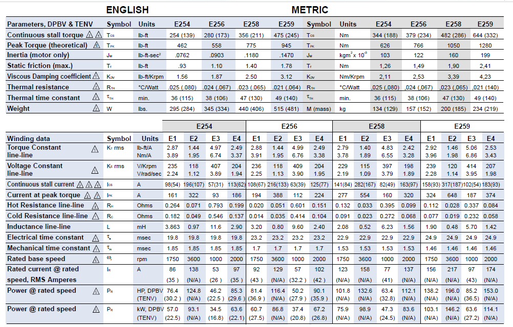
196 hp, 3,600 rpm, 644 Nm (475 ft-lb) PM motor
in Frame E259 (top row), E2 electrical specs (bottom
right)
source --- http://www.powertecmotors.com/e250.pdf
Weight mystery solved
Look at the
weight of the E259 frame motor, it's 515 lbs! This may explain the mystery
of why the Fisker Karma weighs 5,300 lbs. Two of these motors weigh 1,000
lbs, The battery reportedly only weights 600 lbs. Throw in the weight
of the controller and the weight of the 260 hp gasoline motor and you've
got a 2,000 to 2,500 lb drive train!
-----------------------------------------
There was
little technical info on the Fisker site and nothing on the Quantum site,
but I found the links below which have some additional Karma info.
http://www.thetruthaboutcars.com/fisker-karma-brochurespecs-stealth-eco-chic-solar-power/
http://auto.howstuffworks.com/fuel-efficiency/hybrid-technology/fisker-karma5.htm
Fisker could have a lot of company. Plug-in-America (below) has a list (with pictures and status) of nearly 50 hybrid and electric cars in the prototype stage.
http://www.pluginamerica.org/plug-in-vehicle-tracker.html
Tesla Motors lithium ion pure electric cars
Tesla 2 seat roadster
There is a
lithium ion powered car on the market now, sort of (few hundred on road
and production of a few hundred/yr). It's an all electric car, the 100k
Tesla Motors 2 seater sports car, 220 mile range, then plug in (at home)
to recharge (3hr to 37 hr).
Battery
6,800 lithium-ion cells
Off shelf #118650 (18 mm x 65 mm) cylindrical rechargeable 'protected'
lithium ion battery (w/PTC built in)
375 V (open circuit) (supposition)
battery pack weighs 992 lbs
must be massive paralleling (100 cells in series, 65 in parallel)
(assume 3.6V/cell 65 = 6,800 x 3.6V/375V)
For 375V battery pack voltage => 65 parallel strings of 104 cells/string!
(update, comments from Tesla seem to indicate the battery may be divided
into 11 modules horizontally. Meaning 11 (or maybe 10 used for motor)
36V modules made up of 10 cells and 66 (or 60) in parallel)
3.5 hr recharge (high power 480V charger), 10 hr, 240 VAC,
37 hr 120 VAC
Battery lifetime projection is 500 to 700 deep discharge cycles
battery pack is liquid cooled
Battery kwh
56 kwh (37 hr @ 120 VAC, 1.5kw = 55 kwh est)
(56 kwh looks reasonable for 220 mile range, its x3.5 more kwh than
GM Volt)
Tesla's use of small commodity lithium ion batteries achieves a much
higher energy density (150%) than Volt or Leaf. The Leaf is 24 kwh
at 660 lbs (Volt about 400 lbs for 16 Kwh), but the Tesla roaster's
56 kwh battery at 990 lbs weigh only about 2/3 of what it would
weigh if Volt or Leaf type lithium batteries were used.
Power out
185 kw (250 hp) at 8,000 rpm (T vs Speed peak)
281V x 658A = 185kw (guess --- Voltage sag to 25% @ max pwr, like
Prius)
History
Tesla had massive redesign in 07/08 to remove unreliable two speed
transmission and forced out CEO. To restore high torque for 4 sec
0 to 60 motor current rating of motor and inverter (at low speed) was
increased from 640A to 850A. This required higher current IGBT's,
terminals, and wiring. (Poster says (bus) voltage was decreased at low
speed, but don't know what this means. Do they reconfigure
battery pack at low speed, or is he just talking about voltage sag.)
Inverter
200 kw
(aka PEM) 72 IGBT's Yikes! for inverter
and charger (Tesla marketing)
motor rated at 375V, 185 kw the currents are really high (500 A to 600A)
assume 6 igbt's for inverter that's 11 x 6 = 66
Do they have 11 inverters in parallel (!), each with 150A, 600V IGBT's
?
They might! The battery pack is divided into 11 components.
Redesigned for 850A max (@ low speed)
Motor
375 V induction motor (air cooled)
14,000 rpm ! For 380 Nm motor Pmax speed = 4,650 rpm
(Pmax at 185,000 watt/380 Nm x (1/2pi) x 60 = 4,650 rpm)
4 pole (2 pole pair), 100 lbs ("size of a large watermelon")
(my guess is the custom motor has 11 separate windings, with 33 terminals,
to effectively parallel currents from the 11 inverters)
Powertrain 1.5 (one speed gear box) motor in prototype car runs at 850A
(280 ft-lb/380 Nm) (may 2008)
Redesigned for 850A max (low speed torque, 280 ft-lb/380 Nm)
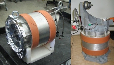
Tesla induction motor
Motor control
digital induction controller designed by Tesla
(In a puff piece in MIT's Technology Review about the lead electronic
designer of Tesla Motors (JB Straubel, age 33) it says Tesla began with
an induction controller they licensed from Alan Cocconi of AC
Propulsion. It was all 'analog' says Straubel, meaning not DSP based, and
gave them a lot of trouble, "no two were alike", it faulted on highway.
The
implication being Cocconi's cirucit design was poor. Tesla replaced it
with a DSP based design of their own.)
I can confirm that Cocconi's induction motor controller design was/is
(probably) out of date. I read an induction control patent of his filed
in 1998, and it looked like the kind of discrete logic design I was
doing in 1978 (VCO as slip generator) twenty years earlier and
prior to DSPs.
Gearbox
single speed gearbox (one fixed ratio forward, + reverse)
(earlier two speed, but it was unreliable)
Dimensions
92.6 in wheelbase (tiny)
2,720 lbs
2 seat
Performance
0 to 60 in ? 4 sec
Top speed
125 mph
Range
220 miles
Don't know the manuf of the Tesla battery, but its easy to find data sheets for #118650 (18 mm x 65 mm) cylindrical rechargeable 'protected' ithium ion battery (w/PTC built in).
Typ rating : 3.7V, 1.8 to 3.0 Ahr, (0.12 to 0.18) ohm
(includes PTC), 46 grams
Energy storage --- 350V (7% sag) x 2.4Ahr x 66 parallel paths = 55
kwh (OK agrees with spec)
Iss = 3.7V/0.18 ohm = 20A. Will deliver 10A peak but this is matched
load so sag is bad (50%)
ESR of 0.12 would reduce sag to 30%
Nobody seems to know the cell being used, but a candiate mentioned (I found
it too) is
Sony 18650G8
Weight --- 6,800 cells x 46 gm/cell = 700 lbs (OK, about 1,000 lbs with
structure)
My summary of Tesla electronics
Found a short
technical article that confirmed my inverter guess. Tesla battery and inverter
is massively paralleled. There are (likely identical) 11 battery modules
eachwith
their own inverter. The battery pack(s) voltage is 375 V formed from about
100 (3.6 to 3.75V) cells in series. The battery pack protections are very
elaborate (? likely costly) with protections on either individual cells
(or groups of six cells) consisting of a series PTC (positive temp coefficient
resistor) and fuses. Some of this protection (like PTC) is built into the
cell by the cell manuf. There is also extensive electrical and thermal
monitoring.
"The commodity cells Tesla uses in its pack all have an internal positive temperature coefficient (PTC) current limiting device, which limits short circuit current on an individual cell level. The device is completely passive. The cells also have an internal Current Interrupt Device (CID) that will break and electrically disconnect the cell in the event of excessive internal pressure caused by over-temperature or other failures resulting in over-temperature." (Green Car Congress 22 May 2007)With something like 66 parallel paths (66 = 11 modules x 6 parallel cell/module) only about 10A peak is need from each cell to supply 200 kw = [375V x 0.8 sag (guess) x 66 paths x 10A peak]. Compare this to the 180A peak the Prius needs from its single series stack of cells. The massive paralleling of the battery pack leads to three advantages.
1) No boost
converter (battery sag acceptable)
375V battery (maybe 20% sag) => inverter (600 V IGBT's => 375 V motor
reported 850A pk means serious battery voltage sag (to near 200V)
2) Series resistive protection can be used (in form of PTC's and fuses)
The massive paralleling of the inverters leads to advantages too. Robust in the field. If an inverter blows in the field and can be isolated, it would hardly be noticed as car still has 10/11 of it full power and range. Big advantage thermally too. Lots of heat has to be dissipated when 660 A are being switched, and this problem is vastly simplified if the source of the heat (IGBT's) are physically far apart. Components for each design are relatively cheap due to high production. Testing is simplified and vehicle repair is simplified.
The use of 11 (apparently) separate inverters (6 x 11 = 66 IGBT's @ 600V ) makes each converter easier to design and to cool. The peak current in each IGBT is about 60A (figured as each inverter peak power is 200kw/11 = 18kw = 300V (with sag ) x 60A). So the inverter are likely conventional using 100A (or 159A) 600V IGBT's.
but, but .... there is the far from trivial problem of combining the current from 11 inverters. This is actually quite tricky and I have seen no clue as to how they did this. The trick is to do this in a reliable robust way. There are ways to parallel inverter outputs with sharing inductors, but the likelihood that the battery voltage of the modules would be different makes this approach daunting.
My guess is the paralleling is done in the motor with parallel windings, a separate winding for each inverter! They say in their marketing material that the motor is custom. Two parallel motor windings are not unheard of, I worked with (? tested) large PM motors wound this way myself. Eleven windings is pretty extreme, but it would be a robust way to parallel the inverters. The major complication is the wiring coming out of the motor. Instead of the usual 3 (or 9 terminals) there are (at least) 33(= 11 x 3) terminals.
Bottom line --- If I'm right that they use eleven identical 100A, 600V IGBT inverters, physically separate, connected to electrically separate battery packs, driving 11 electrical separate windings in a custom 33 terminal induction motor, then this looks to be a pretty rugged, clean (and of course, expensive) package.
update --- Info from Tesla motors seems to indicate the battery division into eleven modules is not what I guessed, that it apparently is divided horizontally not vertically, meaning the 660 cells of each modules are arranged 10 series and 66 parallel outputting 36V. This makes it much less clear as to how the 11 inverters (if there are 11 inverters) are arranged and paralleled.
Tesla Model S sedan
-- luxury model, 300 miles range
(Update 9/29/12)
A production
Tesla model S made its way into the hands of the NYT auto reviewer who
drove it for a week. He says production started in June. SEC filings show
Tesla now plans to make 3,000 model S cars in 2012 (vs 5,000). The reviewer's
car with full 85 kva battery and with some options cost 83k. His overview
is super positive ("One Big Step for Tesla, One Giant Leap for E.V.s"):
"The 2012 Model S, a versatile sedan that succeeds the companys two-seat Roadster, is simultaneously stylish, efficient, roomy, crazy fast, high-tech and all electric. It defies the notion that electric cars are range-limited conveyances. ... Tesla says the car can zip from zero to 60 in 5.6 seconds and tops out at 125 miles per hour, but it was the silent, near-instantaneous bursts from 35 to 65 along the Pacific on California Highway 1 that best demonstrated the Ss otherworldly quality.The reviewer's car had the full 85 kva battery. On a 'restrained' drive (CA in summer) he gets the 'rated' 300 miles (barely), but on another drive where he sees what the car can do, he gets 207 miles with 25 miles remaining. Below is the Model S console with its ridiculous 17 inch touch screen for control of nearly all auto functions almost reaching to the steering wheel. The reviewer says, "The screen size can sometimes seem overwhelming." No kidding! Does web browsing too even while driving! Another new auto 'feature' or 'drawback' depending on your point of view is like many tablet computers (like Kindle) Tesla can 'push' new code into your car. The downside of this of course is that your car is not stable.I found myself sneaking away to Berkeleys winding hilltop roads to experience the smoothness of the electric drivetrain. The half-ton battery pack is under the floor, providing a low center of gravity that helps to give the 4,700-pound Model S its ninjalike handling."
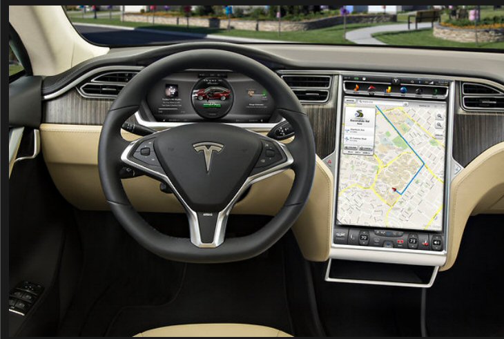
Tesla Model S sedan with 17 inch touch screen master
auto controller
NYT says it can do internet browsing even while car
is in motion!
Talk about (gross) overkill (9/12)
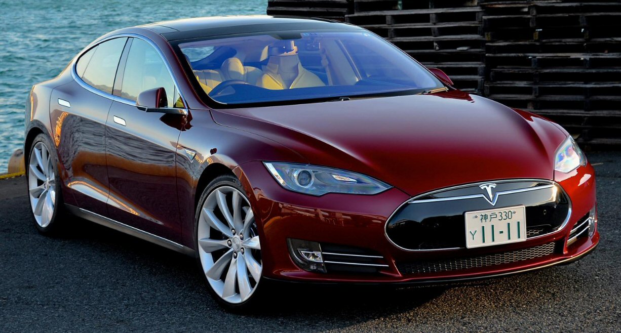
Tesla Model S
(Tesla's 2nd model, 7 passenger (two rear facing seats)
luxury model)
The only thing
the reviewer says about charging is a 240 VAC, 50A service at home will
give you 30 miles of driving per hour of charging. The implication is that
a 300 miles full charge would take 10 hours at (net) 8.5 kw. [240 Vrms
x 50 Arms = 12 kw] This is pretty much consistent with technical specs
(below) which shows the base car has a 10 kw charger (92% efficient) and
charge rate was projected to be 31 miles/hr for a 240 VAC, 40A service.
---------------------------------------------
Tesla Model S fast charger ('Supercharger')
The Model
S 85 kwh battery can be half charged (43 kwh, 150 mile range) in 30 min,
and this fast charger is real because Tesla has installed six of these
chargers. All cars with 85 kwh battery can uses the fast chargers. It took
a little head scratching, but I think I have figured out the basics of
how Tesla charging works. (Tesla doesn't explain how the fast charging
works, not could I find a good explanation online.)
For 30 min, half capacity (43 kwh) fast charging the input power has to be (accounting for losses) about 90 kw. Unlike the Leaf the Model S does not appear to have a separate DC charge port. One reviewer confirmed it has no DC charge port and says it uses a proprietary Tesla charge technique. Pictures of the Model S charge port just show a three pin connector, which looks pretty much like the level 2 charger port on other electric cars. The Tesla web site explains the charger is in the car and that the standard 10 kw charger is fed 240 VAC @ 40A. There is an option to install a 2nd 10 kw charger for home charging at 240 VAC with a total charge power of 20 kw, which adds about 60 miles of range per hour.
The Leaf fast DC charger uses a separate charge port with two high current pins. This DC port is probably either a direct connection to the battery or maybe (for safety) through a diode. For DC charging the charger itself is outside the car and the current that charges the battery has to come in through the cable and connector.
The model S probably has on board for fast charging a three phase 480 VAC input inverter rated at 90 kw. Don't know if this is the same charger used with 240 VAC (one phase). (It might even be the motor inverter reconfigured.) Fed with three phase 480 VAC the output of its front end rectifier would be 150 ADC, since [600 V x 150 A = 90 kw]. The inverter would then drop the voltage in half (to 300 V) and double the current (to 300 A), since [300 ADC x 300 VDC = 90 kw]. Each upper rectifier diode is on 1/3rd of the time and each lower rectifier diode 1/3rd of the time. This means the current in each input pin is 150 A 2/3rd of the time (1/3rd cycle positive and 1/3rd cycle negative), which calculates out to be 122 Arms = [sqrt{2/3} x 150 A]. This is seems pretty high considering the quasi-standard level 2 (240 VAC) J1772 auto connector has pins rated at 70-80A.
I suspect the explanation is that Tesla is not using the quasi-standard J1772 connector. They are likely using a 'heavy duty' version with bigger pins to handle the 122 Arms needed for fast charging. For one thing the pictures of the Tesla port connector don't look the same as the Leaf connector, which I know is a J1772. I see five pins on the Leaf and only four on the Tesla. The Tesla website says the Model S comes with an adapter for charging it at J1772 (80A capable) public charging stations. Translation: 240 VAC (level 2) public charging stations have a cable to plug into J1772 connectors (like on the Leaf), so this confirms that Tesla connector is probably not the same as J1772. (So much for electric vehicle standardization!)
Quick charge overview
The (primary)
problem with quick charging a big battery is really high currents
are needed into the battery. Leaf can get away with DC charging,
which means the connector current is the same as the battery current,
because the Leaf as a 100 mile range car only has a moderate size battery.
The Model S is a 300 mile car, so its battery is x3 bigger, so if the battery
current for a half charge in 30 min for Leaf is 100A, then it's 300A in
the Model S [300A x 300V battery = 90kw or (45 kwh in 30 min)]. The problem
with 300A isn't so much the wire size its the connector on the car.
There are two 'tricks' available to reduce the connector current (and external
charge cable size) both of which I think Tesla is using.
x.5 --- Use an inverter inside the car to half the connector current. The trick here is to input current at twice the voltage. Doubling the voltage has only a minor effect on the design of the connector (pretty much it just increases spacings between pins). In other words put into the car 150A at 600V (derived outside from 480 VAC), and the inverter in the car can convert it to 300A at 300V and input it to the battery.
x.816 --- A further 18.4% reduction in (RMS) current in each connector pin (which is what counts) is available by using a three pin connector and dividing up the power so it is carried in three wires. With AC line this is a basic technique, all high power in the 50-60 hz world flows in three wires, because it minimizes the amount of copper needed. The 18.4% reduction comes about from doing an RMS current calculation for a pin carrying current 2/3rd of the time [.816 = sqrt{.6666}]. This .816 factor reduces the current per pin from 150A to 122A.
Presto chango,
the 'magic of switching circuits' and three phase power allows 122A at
the connector to be converted to 300A at the battery!
---------------------------------------------
(Update 12/12/11)
For 79k Tesla
is licking the range problem in electric cars with a monster 85 kwh battery
pack. They claim 300 mile range. The first 1,000 build will have this battery.
For marketing purposes they advertise a 20k cheaper version (59k), where
they only put in a half size (160 mile range) battery pack.
Model S is coming along, fully speced and priced, with deliveries starting July 2012. Tesla says all 5,000 they can build in 2012 have been pre-sold. From a couple of video I have seen this car looks impressive. The massive battery pack 85 kwh is a flat thin (single) layer of little cylindrical cells standing upright covering the full bottom of the car. This allows the inside of the car to be very open so they have five normal seats and two backward facing child seats. The battery pack is liquid cooled (like Volt). One reviewer said the spacious interior of the Model S is huge compared to the cramped Fisker Karma interior.
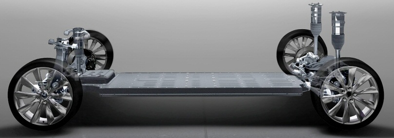
Tesla Model S sedan massive 85 khw battery pack
in a single layer of 8,000 cylinderical cells under car
source --- http://www.teslamotors.com/models/features#/safety
For 59k you get the half size (160 mile range, 42 kwh) battery pack. The price goes up 79k (extra 20k) to double the battery pack to 85 kwh. Car is pretty good size at 116.5 in wheelbase. It has an astounding 130 mph max speed (single speed transmission) with the motor winding up to 16,000 rpm. Torque is flat to 7,000 rpm. 0 to 60 in 5.6 sec, and this is a heavy car. Weight is 3,800 to 4,200 lbs with the weight of the 8,000 cells alone (no structure) of the 85 kwh battery, at 1.6 oz each, weighing 800 lbs. (A special sport version 0 to 4.5sec 0 to 60 will be offered.)

Model S sedan toque vs speed
304 kw (410 hp) @ 7,000 rpm corner
source ---Tesla
web site
--------------------------
Tesla Model S sedan (update 9/1/12)
Tesla Model
S deliveries to public start in "fall 2012". Deliveries of the signature
series (first 1,000?) have begun. Lots of reviewers have driven one. Weight
of car has increased from earlier values and is now about 4,650 lbs. With
a full battery this is a heavy car.
They have two versions of the Model S: regular and for 15k more a Model S 'Performance', which has a higher current inverter (bigger motor too?) that drops the 0-60 acceleration time from 5.6 sec to a blistering 4.4 sec (both specs with full 85 kwh battery)! The Tesla homepage gives the price for the cars with 85khw battery as 70k and 85k (performance). The regular model S with half size (40 kwh) battery is priced at 50k. I am surprised that the 0-60 and top speed both drop as the battery is downsized and car gets lighter. Is this the result of lower peak power available from the battery pack, or I wonder are they lowering the current on the inverter too. It could be this is all a marketing ploy and not driven by the engineering.
85 khw battery 5.6 sec 0-60,
125 mph (max)
60 khw battery 5.9 sec 0-60,
120 mph (max)
40 khw battery 6.5 sec 0-60,
110 mph (max)
This is interesting --- The Tesla Model S battery pack, electric motor, and controller (low end model) are also being used in the new Toyota RAV4 EV.
----
Tesla is now
designing an all electric 58k sedan (Model S) (seats 7) with 300 mile range
for production in 2011/12. This car is premised on an expected improvment
in Li-ion battery capacity of 8% year. Tesla will use the same small lithium
ion cells for the Model S that it uses in the Roadster. The Roadster
battery pack has 150% higher energy density than the batteries in Leaf
or Volt. The Model S will be offered with three different size batter pack:
160, 230, 300 miles. This is rear wheel drive vehicle.
Motor
9 in !! (liquid cooled, induction)
"Three phase, four pole AC induction motor with copper rotor"
362 hp (270 kw) 6,000 to 9,500 rpm
(416 hp (310 kw) performance model)
440 Nm (325 ft-lb), torque flat to 5,800 rpm (const hp 7k to 15k)
[corner 415 nm x 733 rad/sec = 304 kw (410 hp)]
0 to 16,000 rmp (130 mph)
Battery
8,000 lithium-ion cells (300 mile range option)
Off shelf #18650 (18 mm x 65 mm) cylindrical, 1.6 oz, 3,000 mah, 3.7V (10.8
whr)
rechargeable 'protected' lithium ion battery (w/PTC built in)?, liquid
cooled
Packaged in a single layer (upright) that covers the whole bottom
of the car
Battery (kwh)
40 kwh ('standard', 160 mile)
60 kwh (230 mile option)
85 kwh (300 mile option)
Battery weight
1,200 lb (300 mile option?)
Charger
10 kw charge built-in (option to add 2nd 10 kw charge, 20 kw total), 92%
efficient
Charge time
31 miles/hr of charge @ 240 VAC, 40A (62 miles/hr with 20 kw optional charger)
160 miles in 30 min with Supercharger @ 440 VAC
(Leaf can be 80% quick charged in 30 min)
Charge power
(approx) 8 kw, 16 kw, 80 kw (supercharger)
Performance
125 mph (top speed)
5.6 sec (0-60 mph)
Transmission
Single speed fixed gear with 9.73:1 reduction ratio (19" wheels standard)
Wheelbase
116.5 in
Weight
4,647 lbs
Wow, 0 to 120 mph (upgraded to 130 mph) with no gearing. Like the motor in the Tesla Roadster (14,000 rpm) this motor is really going to wind up. (Leaf tops out at 90 mph and I think its motor is then probably at 9,000 rpm)
I see the Model S motor is liquid cooled. I wrote in summer of 2009 that Testa made a mistake in not liquid cooling the motor/inverter in the Roadster as users reported that just a few minutes on a test track produced OT warnings and forced cut backs in performance.
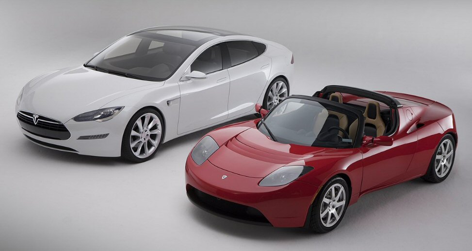
Tesla Model S sedan (left, 116 in wheelbase)
Tesla Roadster (right, 93 in wheelbase)
Incredible tax dollars to Tesla(11/09)
A Washington
Post article discusses the efforts of a CA town to woo Tesla to build the
assembly plant for the 2011/12 electric Model S sedan $57,400. It
mentions also the state and federal tax dollars that have gone to Tesla.
* City (Downey
CA) is waiving 6.9 million in rent on 20 acres (former NASA plant)
* CA is waiving
sales tax (7% to 9%) on equipment bought for the new sedan plant
(to keep the plant in CA)
* 465 million
in low interest loans from Dept of Energy
@ 1,000 cars => 465,000/car
@ 10,000 cars => 46,500/car
@ 100,000 cars => 4,650/car
* Projected
car price of 50K is after a federal tax credit for battery powered cars
---------------------------------------------
NYT takes the Model S for road trip in winter (2/13)
NYT takes
an 85 khw Model S for a little drive in Feb from NYC to CT. On route
are two Tesla 480 VAC charging stations (150 mile range in 30 min, full
charge in one hour says article) located 200 miles apart.
-- 30 degree day. I reached the Delaware charging dock with the battery still having roughly half its energy remaining. I went off for lunch at the service plaza, checking occasionally on the cars progress. After 49 minutes, the display read charge complete, and the estimated available driving distance was 242 miles.
-- At 68 miles since recharging, the range had dropped by 85 miles, and a little mental math told me that reaching Milford would be a stretch. I turned the climate control to low the temperature was still in the 30s and planted myself in the far right lane with the cruise control set at 54 miles per hour (the speed limit is 65). Buicks and 18-wheelers flew past. All the while, my feet were freezing and my knuckles were turning white.
-- After a short break in Manhattan, the range readout said 79 miles; the Milford charging station was 73 miles away. About 20 miles from Milford, less than 10 miles of range remained. I called Tesla again, and Ted Merendino, a product planner, told me that even when the display reached zero there would still be a few miles of cushion. (he makes it)
-- Tesla set a target of producing 20,000 Model S cars by the end of 2013. Some 13,000 eager buyers have reserved 2013 models at prices from about $61,000 to more than $100,000-- I spent nearly an hour at the Milford service plaza as the Tesla sucked electrons from the hitching post. When I continued my drive, the display read 185 miles, well beyond (not really, he needs to drive 158 miles, 27 mile cushion, about 10% of capacity) the distance I intended to cover before returning to the station the next morning for a recharge and returning to Manhattan.
-- ** I drove, slowly, to Stonington, Conn., for dinner and spent the night in Groton, a total distance of 79 miles. When I parked the car, its computer said I had 90 miles of range, twice the 46 miles back to Milford. It was a different story at 8:30 the next morning. The thermometer read 10 degrees and the display showed 25 miles of remaining range the electrical equivalent of someone having siphoned off more than two-thirds of the fuel that was in the tank when I parked.
-- I called Tesla in California, and the official I woke up said I needed to condition the battery pack to restore the lost energy. That meant sitting in the car for half an hour with the heat on a low setting. (There is now a mobile application for warming the battery remotely; it was not available at the time of my test drive.) After completing the battery conditioning process, the estimated range reading was 19 miles; no way would I make it back to Milford.
-- Car is shutting down, the computer informed me. I was able to coast down an exit ramp in Branford, Conn., before the car made good on its threat. The cars electrically actuated parking brake would not release without battery power, and hooking the cars 12-volt charging post behind the front grille to the tow trucks portable charger would not release the brake. So he had to drag it onto the flatbed, a painstaking process that took 45 minutes.
Tesla Model S battery fires (11/8/13)
Press is reporting
three recent fires in Model S. All are due to battery damage. One was (apparently)
a severe crash into a wall and tree in Mexico. The other two were caused
by running over stuff on the road causing damage to the battery from below.
Fire damage in photo looks bad, but then pretty much all cars are a charred
mess after they catch on fire. In both cases here the driver was able to
pull over and was not injured.
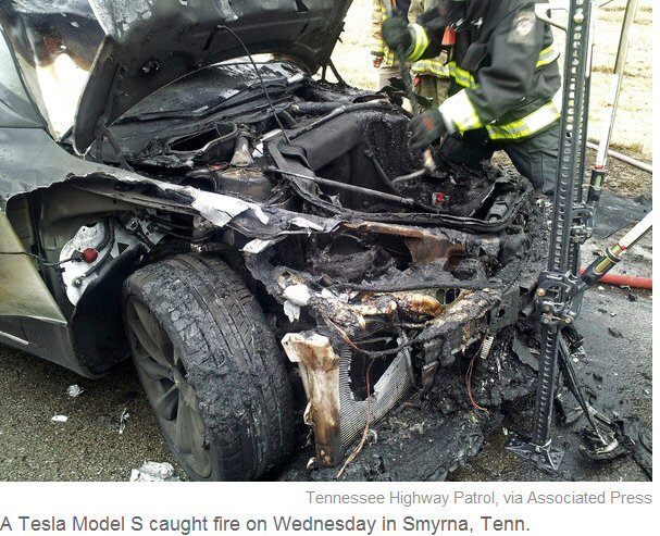
NYT reports this Model S ran over a trailor hitch
on the road
Toyota RAV4 EV with Tesla drive train (9/12)
Toyota has
partnered with Tesla Motors and the first car from this union is about
to go on sale. It is a Toyota SUV, manufactured by Toyota in USA, with
a drive train billed as designed by Tesla. In fact one reviewer says the
Toyota RAV4 EV is using the same battery, motor and controller as
the Tesla Model S sedan, which is just starting production, so the RAV4
EV is really a joint Tesla/Toyota car.
Really?The NYT has just reviewed Rav4 EV and reports it has snappy performance (154 hp) with brisk acceleration even at 75 mph and a usable range of 130 miles. Of course no magic here, the reason it has a long range is it is an SUV and can hold a large battery 41.8 kwh (vs 24 kwh for Leaf), and this (surprise) makes it expensive ($50,000). The standard gasoline RAV4 is 23-25k, or half the price of the electric! The battery weighs 845 lbs and makes the car 470 lbs heavier than the gasoline powered RAV4. The NYT reviewer (and I agree) thinks they made a mistake in not adding a quick charge port (which the Model S has), so it takes ("at least") 6 hr to charge the battery from a 240 VAC line.
When I compare the motor hp in the two cars I find a big difference: 362 hp (270 kw) 6,000 to 9,500 rpm (for Model S) vs 154 horsepower @ 2,800 rpm (for Rav4). If it really is the same motor, it looks like Toyota is being more conservative (or does not need the performance) and has dialed back the maximum speed of the motor to around 3,000 rpm, a factor of 2 to 3 slower than in the Model S. The torque levels are within 15% on the two cars, so it probably is the same motor.
Battery kwh
41.8 kwh
Battery chemistry
Charge time
6 hr (at least) on 240 VAC, 40A
Battery thermal
Battery voltage
Battery location
low, in center of vehicle
DC to DC converter
Range
120 - 130 miles
Peak power
115 kw (154 horsepower) @ 2,800 rpm
Motor
(supplied by Tesla)
Max motor
rpm
Torque
273 ft-lg (sport mode), 218 ft-lb (normal mode)
Max speed
100 mph (85 mph in normal mode)
Motor controller
(supplied by Tesla)
Transmission
Wheelbase
Weight (curb)
4,032 lbs
Comparing
electric car motors --- Fisker Karma vs Tesla Model S (Jan 3, 2012)
A Jan 2012
email to friends (also engineers) comparing the car electric motors including
a head to head comparison of the Fisker Karma with the new Tesla Model
S sedan.
I have been following electric cars closely and there are now quite a few models either in production or quite close. Nearly everyone is using PM motors: Nissan Leaf, Ford focus electric, Coda electric, Fisker Karma electric, and even the GM volt hybrid. It was suspected GM was using induction, but in a technical paper about the car by their engineers both the motor and generator (also used as a motor) are revealed to be PM. The exception is Tesla. Tesla went induction in the existing roadster electric and will go induction in their new model S sedan.DonThe most interesting difference is between the two high speed (125 mph), high power (268 to 300 kw) models: Fisker Karma (designed in US, made in Finland, just started production) and the Tesla Model S sedan (production summer 2012).
Tesla's Model S induction motor goes up to 15,000 rpm, wide constant hp range, single motor about 9" dia, foot long. In contrast Fisker PM motor(s) only go to about 4,700 rpm (with maybe a little field weakening). Since the motor speed and gearing is so low, they need huge motors to get good low speed torque. Their motor is 200 hp PM. Powertec makes a 200 hp, 3,600 rpm PM motor, and it weighs 500 lbs (11" dia and about 30" long).
Fisker has two 200 hp motors! That's a 1,000 lbs of motors, plus 600 lb battery, plus a 260 hp engine (bought from GM), plus a 150 kw generator, plus two 500A controller (bus voltage is only 300V for a 300 kw plant). The power train is probably 2,500 lbs, no wonder this low car weighs 5,300 lbs, and its acceleration is not good even with all this power. The other electric cars run their PM motors to intermediate speeds (7,500 to 10,000 rpm) and a single motor is enough for their modest top speeds and acceleration.
Fisker, like the Volt, runs the battery down the center console of the car making the inside of the car cramped. Their battery (from A123 Systems in MA) can only deliver 500A peak, so when power between 150 kw and 300 kw is needed the engine/generator has to run too. Reviewers are appalled that when the engine starts the car goes from quiet to incredibly noisy.
In contrast Tesla has figured out how to package a massive 85 kwh (Leaf is 24 kwh) as a single thin layer under car (see below). The result is 300 mile electric range and spacious interior, inside is so open they put two jump seats in back and call it a 7 passenger car.
Tesla with an experienced design team in place and field data from the roadster has done almost everything right. In contrast Fisker assembling a design team from scratch with limited time and money for prototypes has done nearly everything wrong. US taxpayer has pretty much paid for the development of both cars. Fisker has a 529 million US Energy loan, and I predict a good chance of being the next Solyndra.
http://www.teslamotors.com/modelsNissan Leaf electric (update 11/22/10)
http://www.fiskerautomotive.com/en-us
-- He said the car's mileage varies wildly. Chalouhi said he can get 100 miles per charge in slow city driving, but only 50 or 60 miles at 75 mph on the freeway. (This is in temperate San Francisco. 50 miles at 75 mph means a full battery charge is depleted in 40 minutes.)(11/22/10) Leaf is a month away from sales and they are playing the same game as Volt, withholding a bunch of specs. EPA has assigned the dollar cost to fuel the car at an assumed electric cost of 12 cent/kwh. At 0.12/kwh it takes 2.30 worth of electricity to charge the battery [2.30 = 0.12/kwh x 80% x 24kwh battery]. Nissan released several detailed milage scenarios with ranges from 62 miles (cold day with heater on, low speed stop and go) to 138 miles.-- An experienced electric car owner says the Leaf dashboard has a huge flaw: it does not report
the remaining charge in the battery! Instead Leaf trys to estimate the remaining miles, but this
number jumps erratically, dropping way down when going up a hill and then popping up again when going down the other side. He says fully charged it first reports 93 miles, then switching to econ
mode it says 102 miles. Within the first 15 miles he sees 102, 84, 66, 82 and 78.-- Reviewer for Slate reports the Leaf drives very well and feels much more like 'real' car than the Prius. Inside it is very quiet.
Nissan released range figures only up to 55 mph. At real highways speed the range numbers are going to badly roll off. My baseline wind resistnace drain is about 10 kw @ 55 mph, but this doubles to 20 kw at 70 mph, and triples to 30 kw at 80 mph. There is only 19 kwh available, so range @ 80 mph could be half @ 55 mph. This is a slow speed, right lane car!
A second performance problem (?) is that with only 80 to 90 kw available and a 3,500 lb car I am calculating 0 to 60 acceleration times of 12.6 seconds (ignoring wind resistance)!! GM Volt is a little heavier (3,800 lb), but I think they have something like 141 kw available using combined torque (via planetary gears) from the motor and generator, so are getting 8.8 sec (0 to 60).
But Wikipedia reports 0 to 60 has been tested at 7 sec, so the conclusion has to be the peak power available has to be far higher than 90 kw, more like 160 kw. (Nope, now I think the answer is a T vs Speed profile with a large constant hp range. see next)
(update 12/2/10) Strong Torque vs Speed roll off needed
for good acceleration
The assumption
of a (simple) triangular power curve for electric cars that peaks at or
near its top speed I now think is wrong, because it leads to poor 0 to
60 mph acceleration. When you have a limited power gear train, to get good
acceleration the power has got to max out at some moderate speed (like
30 mph). This means either a transmission or a motor T vs Speed profile
that rolls way off, giving an approx constant HP range.
More on Leaf acceleration
I read (in
2009 article) that the Leaf will have no transmission, like the Tesla electric.
The Volt when running on its two motors effectively does have a (variable)
speed transmission (but this may only be at high speed). The Pmax point
of the Leaf motor can be calulated from the sped (280 nm, 90 kw) and it
comes out at a low speed indicating there is likely a strong T vs Speed
roll off over much of the speed range of the car.
90,000 watts/280 Nm = 321 rad/sec = 51.2 rev/sec = 3,070 rpm
So my guess is that the Leaf has numbers something like this:
Linear torque range
0 to 3,000 rpm (0 to 30 mph)
quasi constant hp range (@ 80 kw)
3,000 to 9,000 rmp (30 to 90 mph)
max motor speed (@ 90 mph)
9,000 rpm
Torque will now be constant to 30 mph and slowly roll off (1/speed) as power is held roughly constant from 30 to 90 mph. This wide quasi-hp range implies an induction motor or else a PM motor (like Prius) with high inductance, so it can be field weakened.
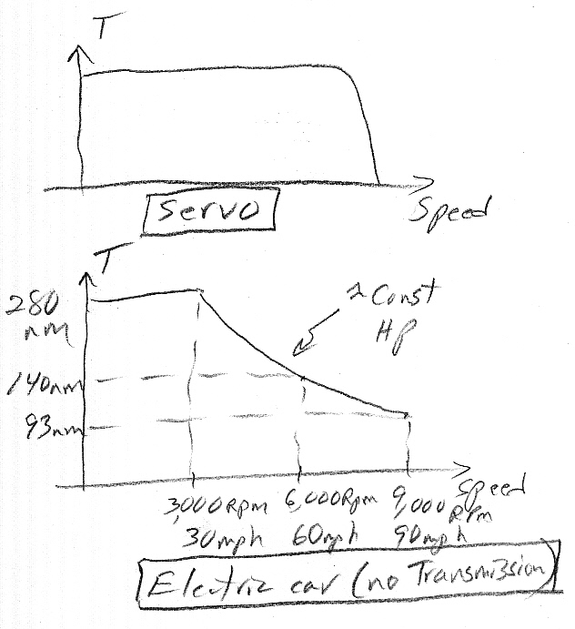
(bot) my sketch showing what I think is the Leaf's
Torque vs Speed profile (12/2/10)
(top) 'rectangular Torque vs Speed used in servos
Let's figure backwards from the measured Leaf 10 sec 0-60 accel time. Assume 4.44 sec 0 to 30 mph and 5.55 sec 30 to 60 mph. This assumes (looking at curve) that av torque in 30-60 mph range is about 80% of peak torque, which stretch acc time by 1/0.8 = 1.25). This puts the following energy into the car inertia:
Linear range
1/2 x 80 kw x 4.45 sec = 178 kj
Const hp range
80 kw x 5.55 sec = 444 kj
---------------------------
total 622 kj
Combined this is 622 kj, or about 9% higher than 572 kj calculated (below) for the 3,500 lb Leaf (3,366 curb plus driver) at 60 mph, so 9 to 10 sec foor 0-60 mph looks reasonable with the above T vs Speed shape. Or add a passenger and lose a few percent to wind and 10 sec for 0-60 rpm looks about right.
0-30 mph accel time (1/4/11)
But Car and Driver
test sheet also shows 0-30 mph at 3.2 sec, which means 30-60 mph took 6.8
sec implying less than half the peak torque meaning a much faster T vs
Speed roll off than constant HP. Here is a check of the 0-30 mph. The kinetic
energy is 1/4th of 60 mph or [572kj/4 = 143kj]. Doing a triangular accel
time with peak power (80 kw) at 30 mph.
0-30 mph 2 x 143kj/80kw (motor) = 3.6 sec
3.6 sec is pretty close to the 3.2 sec Car and Driver reports, so I now suspect the T vs Speed corner at 30 mph is about right, but that torque rolls off faster than my (idealized) curve (above) shows, and this is reasonable when motor losses and wind losses are figured in.
Checking the Leaf motor max rpm from specs (update
6/2011)
Leaf spec:
"16 wheels"
Tires: P205/55R16
89H
Single speed
gear reducer: x7.94
Max motor
speed: 9,800 rpm
Max car speed:
90 mph
I first thought
16" wheel mean a tire dia " tires, but this worked out to be 10,000 rpm
@ 60 mph, or 15,000 rpm max @ 90 mph
16" wheel (dia) => 1,261 rev/mile ?=> 1,261 rpm axle @ 60 mph
1,261 rpm x 7.94 = 10,000 rpm motor @ 60 mph (or 15,000 rpm @ 90 mph)
But looking up the tire spec I find from Firestone below:
Size: P205/55R16 89H, Overall Tire Diameter, 24.90. Revolutions per Mile,
837
Ok, more reasonable. 16"/24.9" = 0.643 x 1,261 rev/mile = 810, but the tire spec says 837 rev/mile so something is a little off (see below). I found a max motor speed on a tech car blog of 9,800 rpm. Figuring the axle speed from motor max speed gives 9,800/7.94 = 1,234 rpm axle @ 90 mph. At 60 mph this would be x0.6666 x 1,234 = 822.6 rev/mile. Good this is just about the average of 810 figured from tire dia spec and 837 tire spec. All the numbers are now close, so it looks like
Leaf electric
motor top speed (@ 90 mph): 9,800 rpm +/- 1% (figured correctly,
using the tire rev/mile spec
the top motor speed is 9,969 rpm (see below))
Straight skinny on tire sizes (update 1/10/12)
Somehow,
not unreasonably, I alway thought that a tire referred to, say, as a 16"
or 17" tire meant that was its dia or radius, but nope, this is not how
tires are sized. Turns out that the reference tire inch number (16", 17",
etc) is an inside dia ('dia of the wheel'). To get the tire dia
the two side walls must be added (which can be figured from the other tire
numbers). But this still does not give the correct rotation rate, because
tires when loaded sqush a little. The operating radius is less than the
radius of an inflated, unmounted tire, it comes from the measured 'Revolutions
per Mile' spec.
For example
Size: P205/55R16 89H, Overall Tire Diameter, 24.90. Revolutions per Mile,
837
Distance per rotation (effective circumference) = 5,280 feet/837
= 6.308 ft (74.699")
Effective dia = 74.699/pi
= 24.096" Ok (3.3% less than 24.90" unmounted)
Refiguring the Leaf top motor speed
At 60 mph
one mile is comvered in one minute, so from the tire rotation spec (837
rotations/mile) the tire/axel is making 837 rotations per min @ 60 mph,
or 1,255.5 rev/min @ 90 mph (top speed). Multiply this by the spec gearing
ratio (x7.94), and we get the max motor speed at 90 mph is [7.94 x 1.255.5
rev/min] = 9,969 rpm
Rule of thumb
The effective
radius is just about 75% of the tire inch number (12/16 = .75), so it's
a good guess that this ratio probably is pretty close for most car tires,
as most car tires seem to have about the same ratio of wheel to side wall.
--------------------------------------
(update 3/30/10) Big news, finally an electric car
has a price
Nissan announced
this week the Leaf will be priced at $32,780 in US. That means when the
$7,500 federal tax credit is subtracted, the car's base price would
be $25,280. I read that CA offers an additional tax credit of $5,000, which
reduces customer price in CA to $20,228. Expected volume for 2011 is 50k
vehicles (high).
No price yet
from GM for the GM Volt. While the Volt has an engine and generator too,
its battery pack is 8 kwh smaller (16 kwh vs 24 kwh). People have been
estimating (guestimating) that the lithium ion battery packs manufacturing
cost about 1k/kwh. I bet 8k easily pays for GM's engine and generator,
which would make GM's drive train costs probably comparable to, or a little
less, than the Leaf.
---------------------
Leaf specs
Nissan is
making big noises (Summer 09) about their electric car, Leaf, planned
for late 2010 about same as GM Volt. Leaf looks pretty similar to Volt
(maybe
little smaller) but the Leaf is a pure electric car vs the Volt, which
is an electric car with a range extender. This may be the first all electric
car mass marketed (outside China). The plan is to build it in Japan and
a Nissan plant in US. Little technical info released yet. In Jan 2010 US
Dept of Energy says it it loaning Nissan 1.4 billion dollars to upgrade
their Tenn plant to make the leaf. (US taxpayer with huge loans, grants,
and tax credits is really subsidizing the electric car development and
early production.)
Battery
24 kwh (lithium ion) Nissan lithium voltage is 3.6V nom
(19 kwh or 80% usable range_
48 modules (w/4 cells/module)
(my guess is 2 cells in parallel for 346V bus = 96 x 3.6V)
360V is nominal battery voltage (1/4/11 update)
DC/DC steps down 360V to 12V for lights, etc.
660 lbs (battery pack, under vehicle)
Range
100 miles (65 to 75 miles realistically, see below)
EPA has measured range at 73 miles (conditions?)
Nissan now says 62 to 138 miles
62 miles --- 14 F (heater on), stop-and-go, traffic jam, 15 mph av
70 miles --- 95 F (A/C on), 55 mph highway (slow highway!)
105 miles --- 72 F (A/C, heater off), commuting, 24 mph av (slow)
(With baseline wind resistance and usable 19 kwh usable capacity
ideal max highway miles vs speed can be calculated)
55 mph x (19 kwh/ 9.7 kw) = 108 miles
60 mph x (19 kwh/ 12.6 kw) = 90 miles
70 mph x (19 kwh/ 20.0 kw) = 67 miles
80 mph x (19 kwh/ 29.6 kw) = 51 miles
90 mph x (19 kwh/ 42.2 kw) = 41 miles (27 min @ top speed)
(Two Tesla customers by driving 55 mph were able to drive
their new Leafs from dealer to home 111 miles. Not really,
article later reveals they panicked and stopped along the way
for a 90 min boost charge (worth 19 miles)
Power out
90 kw (battery)
Motor
80 kw/280 Nm (AC synchronous) (identified as PM motor in one spec)
For 280 Nm motor Pmax speed = 3,080 rpm
(Pmax at 90,000 watt/280 Nm x (1/2pi) x 60 = 3,080 rpm)
(In catalogues 75 hp, 3,600 rpm (induction) motor weighs about 760 lbs)
9,800 rpm @ 90 mph (max) spec (consistent with x7.94 gearing and 24.9"
tire dia)
Wheelbase
106.3 inches
Max speed
90 mph
Vehicle weight
3,500 lbs/1,590 kg (Nissan est)
3,366 lbs ('final spec')
Transmission
Single speed reducer (1/7.94) (roughly 6,500 rpm motor
at 60 mph)
Accel (0 to
60) kinetic
energy @ 60 mph (26.8 m/sec) = [(1/2) 1,590 kg (26.8 m/sec)^2] = 572 kj
Rectangular power 572 kj/80 kw = 7.15 sec
Triangular accel time = 14.3 sec
(It can't be this much of pig, can it?) Nov 2011 blog says 0-62 mph
is 12 sec
(unofficially tested at 7 sec??)
10.0 sec (tested by Car and Driver magazine)
Onboard charger
3.3 kw built in charger supports
level 1 120 VAC @ 1.4 kw, 20
hr
level 2 240 VAC @ 3.2 kw,
8 hr
(Why only 3.2kw?)
(Looks like big mistake here. A 240VAC, 30A 1ph charger
should be able to do 5-6 kw and charge battery in 3-4 hrs, which
is exactly what Ford Focus (w/23 kwh) electric is claiming.)
2nd plug supports external level 3 charger, 480 VAC @ 50 kw,
30 min for 80% charge (causes some additional loss of battery
lifetime if used regularly.) Cost is listed at an absurd 16k!
Battery manuf
Nissan (joint venture with NEC)
------------------------
Battery comparison with GM Volt (1/4/11)
New info on
battery voltage curiously indicated that GM Volt and Leaf both seriesing
the same number of cells [96 (3.6V nom) batteries in series for a 345V
bus]. GM has cells three in parallel (total of 288 cells), whereas
the Leaf has two cells in parallel (total of 192 cells). Since Leaf has
2/3rd the cells of Volt and 3/2 the kwh, that must mean each Leaf cell
is 225% larger than Volt cells. Leaf cells must have 35 Ah rating (= 20,000
kwh/192 cells) vs 15.5 Ahr for Volt cells.
Nissan car manual shows there is a dash display of 'Battery temperature', and say (car) power is reduced to protect battery if battery temperature is 'too low or too high'.
To power the
car on of off you need to step on the brake. That's right to power off
the car you need to step on the brake! Emergency power off (while driving):
hold 'power' button for two seconds, or push rapidly three times.
------------------------
The Nissan
battery kwh is 150% that of the GM Volt (24 kwh vs 16 kwh) and like the
Volt is mounted under the floor of the car. So how does that square with
a claimed milage of 100 miles vs 40 miles (electric) for the Volt. Here's
one way to look at it. If 40 miles uses 8 kwh in Volt, then 100 miles in
Leaf would need 20 kwh. The Leaf has a 24 kwh battery, so this works out
if the Leaf lifetime battery derating is only 17% = [4kwh/24kwh] vs the
50% derating GM is planning.
It just occured to me this may give GM an ace in the hole. If lifetime data on the lithium ion batteries begin to looks good, or battery lifetimes improve in a year or two, then GM with a simple code change can just rerate the Volt for higher electric range (40 => 50, 60 or 70 miles).
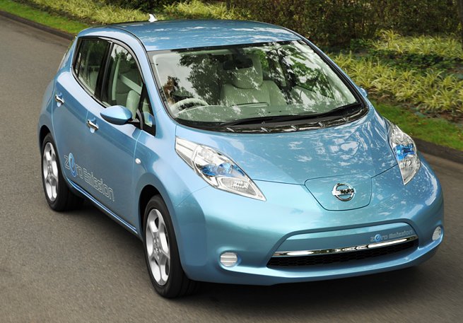
Nissan Leaf (2010) pure electric, 100 miles?
(weird bulging headlights are claimed to "split the
air" reducing the drag of mirrors)
Nissan Leaf battery pack
Unlike the
Volt which has an elaborate liquid-cooled heater/cooler for the battery
(? uses the engine to avoid using the battery hard when it is hot or too
cold), the Leaf battery is air cooled using only a single fan!
The flat battery profile allows the Leaf to have a three seat bench in back. In contrast the hump in the Volt battery divides the back seat in half, so Volt is a four passenger car vs five passengers for Leaf. In an article by a Tesla battery guy he says Nissan experimented with active thermal management for the battery, but it required a hump in the center which would have made it a four seater. He argues that Nissan has under-engineered the battery thermal system, so there is risk it will degrade more than Nissan claims (80% capacity after ten years says Nissan, whereas GM says even with their babying they expect 75-80% capacity after 8 (or 10) years.
CEO of Tesla (Musk) on Leaf battery
-- Tesla uses what Musk described as active liquid thermal control, while the LEAF pack uses an air cooling system. As a result, the LEAF pack will have temperatures all over the place, causing it to suffer huge degradation in cold environments and basically shut off in hot environments, claimed Musk.
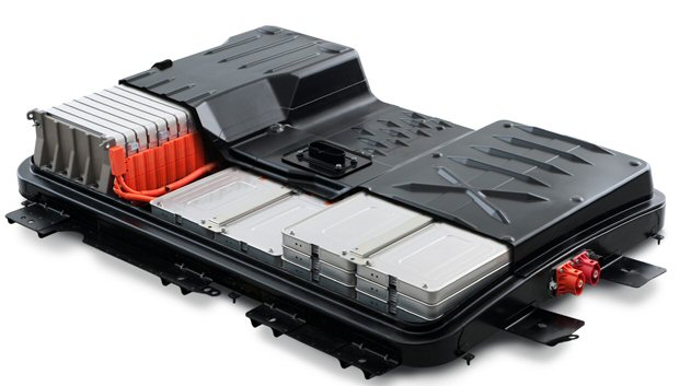
Leaf 99 mpg EPA sticker
There
was a lot of debate about how the EPA would rate the milage of electric
cars. What they have done (see sticker below) is equate the electrical
battery drain (in kwh or joules) for the car to travel a mile to an amount
of gasoline that has the same energy content. I checked standard conversion
tables and 33.7 kwh/gal is what I find, so that must mean the EPA standard
this is not the energy gasoline releases when burned in a combusion
engine, but the total heat energy it released when burned (oxidized)
in oxygen at normal 1 atm pressue.
1 gal gasoline ?==> 34 kwh (really 33.7 kwh) (122 Mjoule)
In round numbers a 33 mpg car burns 3% of a gallon of gasoline to go one mile. An electric car like the leaf @ 99 mpg (eq) uses about 0.34 kwh (1.2 Mjoule), which is 1% of the energy in a gallon of gasoline.
Here's the first EPA sticker for an electric car (Nissan Leaf) from I think Nov 2010.
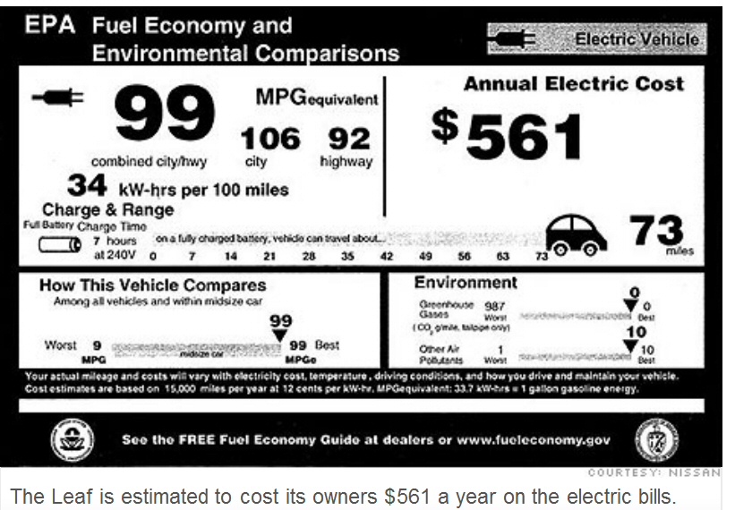
(early version? released by Nissan Nov 2010)
What?
When I look
closely at the numbers on the sticker, I see all kinds of problems.
For a starter how can it take 7 hours to recharge the battery at 240 VAC? Standard 120 VAC, 15A circuit can supply 1.5 kw, so 240 VAC @ 30A should be able to supply x4 (twice voltage, twice current) or 6 kwh. It should be possble to recharge fully in 3-4 hours, which is just what Ford Focus electric (23 kwh battery) is saying. What did they do design a half wave charger! (Maybe they did, 7 hr is the Leaf spec. Their built-in charger has only a 3.1kw rating.)
If the car can go 73 miles (presumably at the combined city/highway 99 mpg), then it must have used
(73m/99 mpg) x 34 khw/g = 25 kwh
What? This car has a 24 kwh battery and the 73 miles appears to be a realistic range, and the usable kwh can't be more than 80% (19.2 kwh) of capacity, can it? Or if I figure another way it looks like maybe the math is wrong, that they used 11 cents per kwh, not the 12 cents it says in the footnote.
EV-1 specs
For comparison
with the Tesla electric here's info on the first mass produced car (about
1,100 built), the GM EV-1 about a decade ago (manuf 1996 to 1999).
Battery
26 (12V) lead acid (standard)
312 volt (26 x 12 = 312V)
18.7 kwh (60 amp-hour x 312V = 18.7 kwh)
1,310 lbs
55 to 95 mile range
26 NiMH (option)
343 volt (26 x 13.2 = 343V)
26.4 kwh (77 amp-hour x 343V = 26.4 kwh)
1,147 lbs
75 to 130 mile range
Recharge
6 hr @ 220 VAC (6.6 kw)
23 hr @ 110 VAC (1.2 kw)
inductive (Magne Charge) with printed circuit board primary
Motor
102 kw (137 hp) induction motor
150 Nm @ 0 to 7,000 rpm
[(7,000rpm/60) x 2 pi x 150 nm = 110 kw]
Inverter IGBT inverter
Weight 3,086 lb (w/lead acid batteries)
0 to 60 mph 8 sec
Estimate of battery current at peak power
Matched load
current = 872A (est) Assume GM at peak power loads battery
like Prius (x3 matched load) or 1/2 matched load current. 312 V x
0.75 (sag) x 436A= 102 kw (motor rating). (Confirm: found a 40 Ah 12V lead
acid vehicle battery with ESR = 8 mohm, which is a matched load current
of 750 to 800 A.)
BMW Mini-Cooper
electric proto (3/28/10)
According
to NYT the only electric car on USA roads in any numbers (450) besides
the Tesla Roadster (> 1,000) is the BMW Mini-Cooper electric (Mini Cooper
E). The company is leasing them for one year to 450 customers in New York,
New Jersey and greater Los Angeles. Leases started in summer 2009. These
are test cars not real production electric cars. They are EV conversions
of the Mini Cooper with the battery located where the back seat would normally
go. Range 100 to 120 miles (real world).
The monthly rental fee includes a 220 VAC charger than can recharge the batter in 3-4 hours. This is smart. Recharging from 120 VAC as GM is planning is a big mistake. The Times adds, "Charging from a household outlet takes up to 24 hours (others say 21 hours)." (check: 21 hr x 1,500 watt = 31.5 kwh). The implication of charging x6 faster from 220 VAC is x2 voltage and x3 current, in other words 220 VAC @ 45A.
"Several companies, including BMW and Nissan, are developing quick chargers that can fill batteries to 80 percent capacity in a half-hour or less."
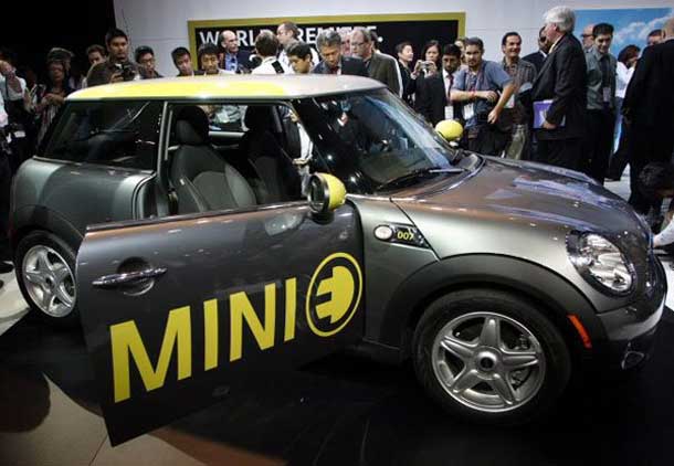
Cold weather problems
"As for owner
complaints, the biggest by far is reduced range in cold weather."
(NYT) Oh, yea. At least Cooper (sort of) faced up to the temp problem of
the battery by leasing cars in NE not just in the south. However, NY/NJ
in winter is not like Minnosota! Range nominally is 100 miles. One customer
says he got 128 miles once. "Running the Minis battery-powered heater
(or air-conditioner) cuts the range as well."
Towed! After only 87.8 miles sheesh! he wrote in a blog post at myemini.wordpress.com. Another lessee blogged on G.M.s Volt site that his Minis power gauge fell to zero after just 55 miles on a 23-degree day. BMW acknowledges that range can drop as much as 30 percent in frigid weather." (No mention of cold weater derating or problems on Mini E web site.)Data from Mini E web site and early 2008 BMW press release. A 2008 article notes "AC Propulsion eBox electric vehicles which also sport a 5,088 lithium-ion cell battery with 35 kwhr of capacity" and asks if conversion is really by AC Propulsion. BMW claims the mini E handles as nimbly as a gas powered Mini, but one leaser who has both types of Mini's says not true, the battery version is not as nimble.
Battery kwh
35 kwh
Battery
5,088 lithium-ion cells (grouped into 48 modules, air cooled)
Battery voltage
380 VDC
Range
156 miles ideal (109 city/96 hwy)
Power out
150 kw (motor)
Max speed
95 mph
Wheelbase
97.1 in
Vehicle weight
3,230 lbs
Consumption
0.22 kwh/mile (city)
Recharge
3 hr (240 VAC, 48A rating)
4.5 hr (240 VAC, 32A rating)
26.5 hr (110 VAC, 12A rating)
Note, there is no battery derating in these prototype cars to extend battery life. You can bring the battery charge down to (about) 0%. (In contrast GM Volt is only going to use only half the capacity of its 16 kwh battery.) "To protect the battery" they say they reduce peak torque when the battery charge is less than 10%. (sounds more like a trick to help get you home). One leaser with a 60 mile commute had a 2nd 240 VAC charger installed at work.
From the numbers it does look like BMW just licensed the electric drive train from AC Propulsion. This either means BMW is not really serious about electric cars, or perhaps this was just good engineering. Buy a proven (if unsophisticated) electric drive train from a 3rd party to get a test fleet of electric cars on the road fast. Then you have time to do your own electrical design, convince management about electric cars, and perhaps have an edge over other manufacturers because you will have feedback from a substantial electric fleet in the hands of the public.
Good news for BMW is that the NYT reports that a lot of the first year renters, who have driven it now for nine months or so, like the electric Mini Cooper and want to continue to rent it.
BMW ActiveE (update Feb 2012)
BMW is showing
a lot of good engineering in their development of an electric car. The
hundreds of small MiniE electrics that BMW leased was on-the-road prototype
#1. It has now been replaced by a larger sedan on-the-road prototype #2
(ActiveE) of which BMW will make a 1,1000 (700 to USA) again to be only
leased (not sold). While this car is more Leaf like, ActiveE still shows
signs of being a partial conversion. NYT says the company plan is for a
production electric car in a couple of years and expects to go to
a carbon fiber body to cut the weight substantially.
Battery kwh
32 kwh (992 lbs)
Battery
192 cells (liquid heated/cooled)
Range
100 miles ideal
Power out
125 kw (motor)
Vehicle weight
4,000 lbs
Recharge
4 hr (using built in 7.7 kw charger, 240 VAC)
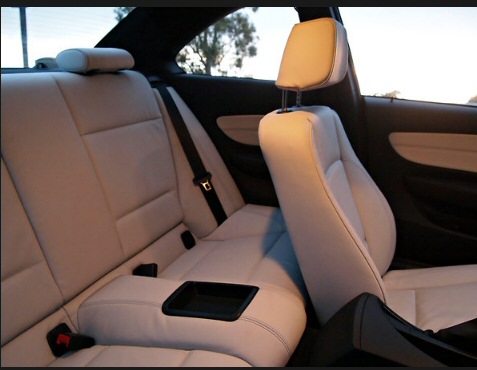
BMW ActiveE (electric prototype #2)
Front seat hits rear seat when pushed back for 6 ft
4 driver!
One pedal control
BMW, like
Tesla, as adopted the strategy of fairly heavy regenerative braking when
the foot is lifted off the gas pedal, no more coasting. The NYT reviewer,
who normally drives a Leaf, says it takes a little getting used to, but
once he did he liked it a lot. You learn when to lift off the gas to come
to a stop at a traffic light, he says. Essentially you can drive the car
with one pedal, do much of your braking without having to move your foot
to the brake pedal. BMW speaks favorably of 'one pedal control'. In contrast
the Leaf drives more like a normal car, you got to put on the brakes on
to stop!
Mitsubishi
MIEV electric car (12/25/11)
As of Dec
2011 Mitsubishi is runnng a (short) TV commercial for a pure electric available
in USA early 2012. Wikipedia says this car has been on sale in Japan since
2009. It's a tiny car about the size of the Mini-Cooper electric,
but with a smaller battery and and less performance. Mitsubishi has got
the same size battery as the Volt (16 kwh), but because it's so light (2,580
lbs) its range is 62 vs 35 - 40 miles. While the Mitsubishi is a lot lighter
than the Mini-Cooper, it's very odd that the motors in the two care are
different by a factor of three (49 kw vs 150 kw)! I suspect the lighter
weight of the Mitsubishi may be because it was designed as an electric,
whereas the Mini-Cooper spec is for a normal Mini-Cooper converted to electric.
Battery kwh
16 kwh
Battery
88 cells (eq to 3.75V/cell)
Battery voltage
330 VDC
Range
62 miles (EPA)
Power out
49 kw (motor, AC synchronous, PM)
Max speed
80 mph
Wheelbase
100.4 in
Vehicle weight
2,579 lbs
Recharge
50 kw, 80 kw (DC? , Level 3charge) option
7 hr (240 VAC, 15A rating) option
22.5 hr (110 VAC, 8A rating)
Ford Transit electric van (proto) (3/31/10)
Advertized
as the Ford's first production electric vehicle in USA will be a Turkish
made high profile small van transformed to an electric by Azure Dynamics
in Michigan. It's to go on sale at the end of 2010 with sale to commercial
customers. Battery pack is on the underside of the vehicle. It appears
that Ford is doing something similiar to what BMW did last year, going
to a 3rd party electric developer to do a rework get electric vehicles
out into the field quickly for feedback.
Battery kwh
28 kwh
Range
80 miles
Max speed
75 mph
Battery voltage
336V
Recharge time
6 to 8 hr @ 240 VAC
Battery weight
600 lbs (reduces van load capacity from 1,600 lbs to 1,000 lbs)
Battery supplier
Johnson Controls-Saft
Motor type
Induction motor (air cooled)
Motor controller
600V IGBT inverter with DSP based field vector control
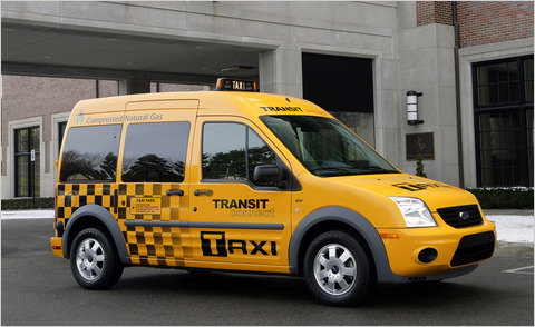
An interisting question is who did the electric work on the Ford Fusion hybrid which gets great gas milage. Azure Dynamics is located in Michigan and has been around for 20 years doing electric vehicles (so they say). Did they do the Fusion or did Ford do it in-house? Azure's web site says they have worked with Ford before, but list only a couple of buses. (Ford web site says the Fusion electronics were developed in-house.)
Ford Focus electric (update 1/9/11) (update
11/6/11)
(update 5/6/12)
NYT reviewer reports on several days driving production Focus electric
and says it goes on sale in a few weeks. He owns a Leaf, and he likes it
that the Focus with its built-in 6.6 kw charger charges in half the time
of his Leaf (20 miles/hr vs 10 miles/hr at a public charging station).
He makes a point of this by saying he could take a longer trip than he
could with the Leaf to a place with a public charger that he uses while
he has lunch so he can get home. This is going to be more important as
more public charges become available.
Focus electric is build on same production line as regular Focus, so the result is the battery pack is not well placed. Much of it is in the trunk, which it nearly fills. The reviewer hates the display of remaining battery charge in both the Focus and the Leaf. He says Leaf owners call the display of remaining range the 'guess-o-meter'.
His electric
rule of thumb --- 4 miles of range per kwh under favorable conditions and
more like 3 miles with air conditioning, or up/down hills or in cold weather.
-----------------------
Price of all
electric Ford Focus with its liquid cooled 23 kwh batttery is to be $39,995
vs all electric Leaf with its air cooled 24 kwh battery at $36,100 (after
a recent price increase). The Focus price is identical (to the dollar)
to the GM Volt electric-hybrid.
Ford Focus electric (available 4th quarter 2011) is apparently a direct competitor to the Leaf. Its all electric and the same physical size with almost the same size battery 23 kwh (vs 24 kwh in leaf). The car's top speed is only 84 mph, not much of a highway car. The 'new thing' that Ford marketing is touting is not new. They say the Focus will offer a 6 kw charger (optional) that will be able to recharge the car in 3-6 hours, but I read in the Leaf manual that they have (or will have) a 440 VAC charger that can 80% charge the battery in 30 minues.
The Focus electric will use (like GM) a liquid-cooled active thermal management system for the battery. (Nissan now says it too for "higher end offerings" and for use in Middle East it will go to active battery thermal managment.) A Ford engineer is quoted,
All-electric vehicles do not have a conventional engine on board, so it is critical we maximize the performance of the battery under various operating temperatures.And this is interesting
The second cost-cutting measure is Fords use (in the Focus) of generic pre-made electric car technology. In other words, Ford is using a system already developed by Magna International, a major global auto supply and technology firm, which has been looking for a carmaker to use its new pre-packaged electric car architecture, including motor, transmission, motor controller, lithium ion battery system and chargerOne automotive writer says Nissan is misleadingly giving only the EPA city number (LA4 cycle), which is low speed driving (20 mph av). A Chinese electric, Coda, quotes 120 miles city and 90 miles, highway (US06 cycle) with a 33.8 kwh battery. Scaling this would say the Nissan range realistically is more like 65 to 75 miles, which looks to be scarily low, since in a pure electric if run out of juice your stuck. Here is the EPA city drive cycle:
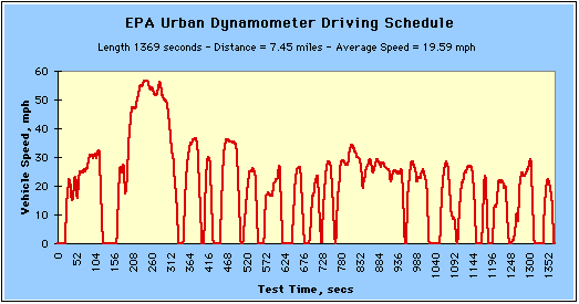
7.5 miles (23 min), mostly 30 mph stop/start (only
2 min above 40 mph), avg speed of 19.6 mph
(9/30/09 update)
Nissan is
talking about having 20,000 Leaf pre-orders by the time car goes on sale
in late 2010. But GM may only make 10,000 Volts in 2011 (from Volt official
web site), is not taking pre-orders and has not announced launch locations.
(3/28/10) update)
CEO of Nissan-Renault
continues to make big noise about electrics. He claims his company is the
only car company investing big bucks in electric car production. The numbers
being thrown around are Nissan-Renault spending three billion pounds over
the next decade to ramp up to 500,000 electric cars per year. BBC has a
video story about a specific Nissan plant in UK that is ramping up to build
50,000 Leafs/yr by 2013. Last line of the video, "The price of which (Leaf)
has yet to be revealed!"
Ford Focus electric(3/31/2010)
(5/4/2011 update)
So now it's May 2011 and where is the all electric Focus? Well, there's
a picture in the new Ford marketing booklet, but it says production begins
late 2011. Still a 23 kwh battery. Marketing is featuring 3-4 hr charge
time (with 240 VAC) claimed to be twice as fast as Leaf. Car looks nice,
and a nice touch is an illuminated ring around the charge port.
The Focus charge ring is pretty sexy. When you plug in it rotates a couple of times to indicate charging has begun. It then indicates the state of charge of the battery, flashing when a quadrant is charging and on steady when that quadrant is charged.Technically I am curious to see if Ford is going to go the route of Volt with elaborate temperature and derating protection for the battery, or like the Leaf with a barebones approach, the battery either lasts or it doesn't. A 1st generation electric car is going to become obsolete pretty fast, its effective life is short, so worrying about extending battery life to 8-10 years, like in the Volt, while it will later be important, may not be so important with these 1st generation cars. I am beginning to think Nissan is taking a good risk.
Looking on the web site in the photo I found the battery cooling answer ---- "It uses an advanced active liquid cooling and heating process to regulate battery temperature and help maximize battery life." From above it looks like the battery is under the rear seat and trunk. The thing in the center, away from the heat of the engine and battery, is probably the inverter.
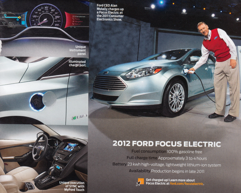

from Ford Focus video 5/11
(rt is front)
-- Lower price: Based on current plans, the home charging station with standard installation is expected to retail for approximately $1,499, as much as 30 percent less than competitors systems
-- Faster charging: With its maximum 32-amp charging capability, Focus Electric owners with the 240-volt home charging station can get a full charge in as little as three to four hours charging in half the time as the Nissan Leaf. (Note the mini-Cooper charger (for its 35 kwh battery) has both 32A and 48A @ 240VAC rating.)
-- Nonpermanent installation: The charging unit plugs into a 240-volt outlet instead of being hard-wired into the electrical breaker box, making removal and replacement a simple unplug and plug back in operation in the event the owner moves

Ford focus 240 VAC, 32A charger
(designed to plug into a 240VAC outlet)
NYT says Focus will not be compatible with fast DC
chargers
-- Single point
of contact for purchase and installation: Best Buy and Geek Squad will
sell, deliver, install and service the home charging station, including
contracting any additional home electrical needs for 240-volt service.
Best Buy also will handle warranty and repair claims for the charging station
-------------------------
Early 2011
Ford will begin selling an all electric version of the Ford Focus. Just
like the electric Transient van was outsourced, the electric Ford Fucus
design has been outsourced to Magna Internationa, a Canadian company. The
Focus, unlike the GM Volt, is an all electric with about 100 mile range.
This looks to be a real production car with estimated first year volume
of 5k to 10k vehicles.
Battery kwh
23 kwh
Charge time
3-4 hr (using 240 VAC)
Range
100 miles (80 miles in prototyptes)
Max speed
84 mph
Peak power
105 kw (141 hp)
Batteries
98, air-cooled, 60 Ah Lithium-ion
(98 modules x 3.91V x 60 Ah = 23 kwh)
Battery voltage
383 VDC (est from 3.91V x 98 modules = 383 VDC)
Motor
92kw, PM motor (92kw motor from NYT article 11/11, conflicts
with peak power of 105 kw)
Max motor
rpm 7,500 rpm
Torque
236 lb.-ft. / 320 Nm
Motor controller
600V IGBT s @ peak 365Apk nom (probably)
Transmission
single speed gearbox
Wheelbase
104 in
Weight (curb)
3,421 lbs
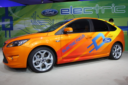
Coda electric (update
June 2012)
NYT obtained
a car for a week of test drives, billed as a bare bones electric car that
goes further. Looks like the car is now for sale (you can schedule a test
drive). This car's claim to fame is (supposed to be) 50% more range for
the same money as Leaf and Ford focus because it has a 50% larger battery
(36 kwh vs 24 kwh). Well the NYT test car had only a 31 kwh battery, the
36 kwh battery will not be available until the end of the year.
To say NYT was unimpressed is an understatement. For one thing the body was designed for the domestic Chinese market and it shows: lots of cigarette lighters and no cup holders, pedals too close together and not placed right, no standard shift knob, instead a weird dial (that continues to spin at end of travel). Plus annoying growels and whines, like getting your teeth drilled said one perspective buyer! "When starting out, the electric motor groans in low deep spasms as speed builds. At higher speeds, wind noise and buzzing intrude. The ride is harsh, giving passengers intimate knowledge of every imperfection in the road."
The latter does not surprise me. Designing a car is a huge job, even one like this that is sort of subcontracted out. A new design team doesn't have the experience, time, money or facilities to do a good and through design and most important to properly prototype the car and wring out its bugs. What ends up getting sold when the car first goes on the market is effectively an early prototype.
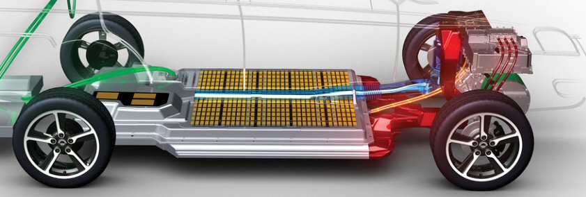
Coda battery 31/36 kwh placement
(right is front)
Weird programming too. When the NYT driver does a 0 to 60 acceleration tests he gets 19 sec vs 9.5 sec spec. Turns out when battery capacity is low the car (apparently without telling you) lowers the acceleration. I like the battery placement, it's similar to the new Tesla sedan.
(update Nov 2011)
New electric
cars keep popping up out of nowhere. Just beginning production is Coda,
a 5 passenger all electric. This is a USA company that Wikipedia says semi-manufacturer
a car. They are building an electric version of a gasoline car apparently
made in China, but designed in Italy and licensed from Japan! The battery
is coming from China. It's privately funded to the tune of 200 million.
Recent story says the company at its LA plant has 220 engineers, technicians
and corporate staff.
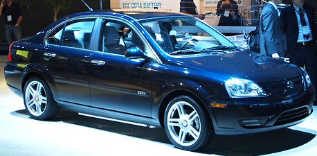
Coda 5 passenger sedan
102.4 in wheelbase, 36 kwh battery, cost 40.8k
The 'claim to fame' of this car is that it has a 36 kwh battery and sells for 40.8k. It's battery is 50% bigger than the Leaf, so whereas the Leaf does about 80 miles, this car will do 120. It has on board a 6.6 kw charger, so it can be recharged in 6 hours from a 220 VAC charger.
This a Ford Focus electric competitor. About same size and power (hair smaller), but with its large battery it is 250 lbs heavier, so its going to be a bit sluggish. The top speed at 85 mph is low.
Battery kwh
36 kwh (728 cells, 104 series x 7 parallel?), 870 lbs
(31 kwh)
Battery chemistry
Lithium iron phosphate (LiFePO4)
Charge time
6 hr (6.6 kw charger on 240 VAC)
Battery thermal
Air-cooled Active Thermal Management (translation: fan cooled)
Battery voltage
333 V
Battery location
between front and rear wheels
DC to DC converter
2.2 Kw @ 13V
Range
120 miles (manuf claims 150 miles)
Peak power
100 kw (134 horsepower)
Motor
PM, 100kw peak, 60 kw cont (UQM® PowerPhase® electric motor)
Max motor
rpm
Torque
221 lb-ft (300 nm)
Max speed
85 mph
Motor controller
(supplied by UQM)
Transmission
single speed (6.54 to 1 gear ratio, 17" wheels)
Wheelbase
102.4 in
Weight (curb)
3,670 lbs
UQM motor
+ controller supplier
Coda is buying
the PM motor + controller from UQM, which manufactures it in Colorado.
(40,000 drives annual production capacity). In last quarter revenue was
2M with reported loss of 1.5 M as they geared up to manuf in volume the
system below. Looks like this small company is betting big on the Coda.
This year they received 4M from DOE for R?D on non-rare earth PM motors
for electric cars. Jon F. Lutz is VP for engineering. (motor and drive
packaging look very nice)
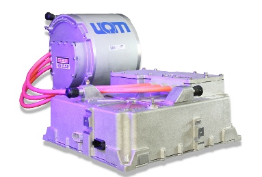
UQM 100 kw peak PM motor + controller (USA)
model PowerPhase Pro 100 (used in Coda electric 5
passenger sedan)
Think city car
One of the
first lithium-ion battery electric cars expected to reach production status
in US (late 2010) is a tiny car from Norway called the THINK city. The
THINK company in Norway claims to have been in the electric car business
for 17 years and that its latest car is a 5th generation design. They have
1,200 electric cars on the roads in Norway with the factory capability
to produce 16,000/yr. However, missing from the THINK company bio is info
from NYT which says THINK is emerging from bankruptcy, and this caused
them to close their Norwegian plant and shift production to Finland. First
cars sold in USA will be imported from Finland. THINK has contracted to
reopen an old plant in US (Elkhart Ind) in early 2011, spending 43 million
(Dept of Energy loan!) for a facility upgrade, with production capability
of several thousand a year.
It was reported in 2008 that THINK was partnering with A123Systems and Ener1 for lithium-ion batteries. Ener1, Thinks biggest shareholder and battery supplier, is headquartered in Indiana. However, a Jan 2010 article in NYT says THINK announced this week that EnerDel, which holds a large stake in Think, will initially become the exclusive supplier of lithium-ion batteries for the car in the United States. (Is EnerDel and Ener1 the same company? Yes, EnerDel is a subsidiary of Ener1.) EnerDel battery model for THINK is E350-25 with prismatic (rectangular) cells. It might be 24 kwh, because this is known to be the size of some EnerDel vehicle battery packs, and it looks about right for the size and mileage. EnerDel got $118 million from US Dept of Energy.
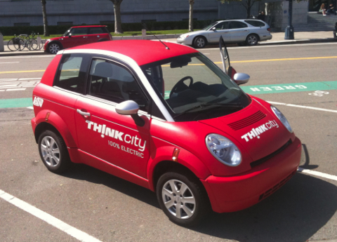
THINK city --- 100 mile two seater Norwegian electric
car (available late 2010)
It's reported in the press the car has a 112 mile range and top speed of 70-75 mph. Incredibly the THINK web site, while offering the car for sale in Norway and Austria, has no specs and virtually no technical info at all. It doesn't even say its powered by lithium-ion batteries! The cost, mileage, ? weight of this little car would provide an interesting electric car bench mark. Jan 2010 NYT article says cost of car will be $30,000 after incentives. Yikes.
Fast charging
THINK is pushing
'fast charging', which is very interesting. They have contracted with a
CA company (AeroVironment) for a roadside 'fast charging' station that
(the claim is) provide a 0% to 80% battery charge in 15 minutes. Details
not announced, but it is likely it is a charger run from a 440 VAC line,
a so-called 'Level 3' charger. (PG?E installed a 440-volt fast-charging
station in 2009 off Interstate 80 between San Francisco and Sacramento
as a test facility.) Cannot find kwh of the THINK battery.
Tesla's new sedan (as of 2009) was to be designed to 'fast charge' in 45 min from 480 VAC (4 hrs from 220 VAC). Nissan (in 2009) was taking about a 26 min 'fast charge' for a 100 mile electric, probably the Leaf.
Ford Focus (all) Electric (5/09)
In probably
a smart move I read that Ford is designing its new European designed Ford
Focus to be powered by either a conventional motor or an all electric drive.
This will provide economies of scale. The conventional model to go on sale
in 2010 followed by the electric version for fleets in 2011. The car design
(or more likely just the electrical subsystem) has been contracted out
to Canada-based auto parts and assembly supplier Magna International. Well
really Magna pitched the electric car to Ford and retains the rights to
sell it to other car manufacturers too.
Only preliminary info is available.
Battery
26 kwh lithium ion
Motor
400 volt
Range
100 miles
GM Volt claims 8 Kwh (of 16 kwh battery total) yields a 40 mile electric range. While the Ford Focus may be a little lighter than the Volt, still to claim 100 mile range from a 26 kwh battery means battery manufacturers will have pretty much solved the lifetime problem by 2011 as there is very little excess capacity for lifetime derating.
Electric reliability
Ford escape
SUV (300V battery pack) has been used in taxis. A taxi manager at a battery
conference recently said some hybrid Escape taxis have now racked up 300,000
miles and the battery pack has proven to be reliable. On the other hand:
"General Motors discovered the batteries already installed in 9,000 2007 model Aura and Vue hybrids were likely to fail prematurely. So a recall was launched in February, and it is still not completed. Batteries for those vehicles had to be replaced before more could be made available for the 08 hybrid vehicles" (Jan 2008). (I read the GM batteries were US made)
Electric car 'fuel' mileage
Here is a
little exercise comparing 'fuel' costs of electric cars to normal gasoline
cars. Obviously there is a lot of assumptions here, but this gives an estimate
of incremental cost per mile. I'll figure 'fuel' costs to drive 100 miles.
Gasoline cost
$2.70/gal
Gasoline mileage
30 miles/gal
Electricity cost
17.5 cents/kwh (Boston area kwh rate)
For a gasoline car getting 30 miles/gal to go 100 miles the car burns 3.333 gal of gas.
100 miles/(30 miles/gal) x 2.70/gal = $9.00 (@ 100 miles)
GM says its GM Volt will go 40 miles in electric mode using 8 kwh (half the capacity of its 16 kwh battery), hence the electricity cost to recharge the battery 2.5 times is
2.5 x [8 kwh x 0.175/kwh] = $3.50 (@ 100 miles)
electric/gas = $3.50/$9.00
= 39%
Hence the 'fuel' costs for an electric car are about 40% of the fuel costs of a (similar) gasoline car at $2.70/gal (about 25% @ $4.00/gal).
Electric
car batteries and range (5/11)
A friend sent
me a news article about a professor developing a fast charging battery
and asked if this was the solution to electric car range problem. Here's
my
reply.
The Ecocomist magazine had a similar story about a fast charging battery a few months ago. I think I posted to it because fast charging is mostly hype. Most of these batteries don't exist, but let's ignore that and assume they do. If the battery ESR can be reduced, it's mostly a good thing because the battery is more efficient and runs a little cooler. (However a poster did point out that a big battery with a very low ESR could be considered a bomb, and he may have a point.) In fact some pretty fast charging large lithium ion batteries, 10 min recharge (!) say their manuf, have been on the market for quite a while, but when you look at products you see much longer recharge times. Why? Comes down to basic physics and cost.So what's the solution he replied, just better batteries? I continued:1) Current/Wiring
Your 'basic' electric car has 24 kwh battery and a battery voltage in round numbers of 300VDC. To recharge this battery fully in one hour I = 24,000 watt/300V = 80A. To
recharge it 1/10th time (6 min) makes the current 800A. 6 min recharge means all the wiring in the charger, battery, car wiring and its plug would have to be rated for 800A! (The
standard plug adopted by all the electric cars has about a 70A rating, though Nissan has also included in the Leaf a 100A connector for 480 VAC charging)2) Power source
For a 6 min charge the power is 24kwh/0.1hr = 240kw (1/4 Mwatt). Either a charging station pulls 1/4 Mw/car in real time from the grid or it needs local storage, say the equivalent to x10 cars, or 240 kwh. If the cost of a car battery is 10k, then obviously for 100k you could assemble a 240 khw battery stack. Large sodium sulfur batteries at 2 Mwh each are in production by a Japanese company for load balancing. It takes a small building to hold a 2 Mwh battery. All this cost might (might!) make sense for 'electric gas stations', but it's not something you can afford to do at home.3) Electric gas stations
A poster to the Economist article pointed out that the concept of 'electric gas stations' may not make any sense. You can't get gasoline at home, you have to go to a gas station. But in an electric car, if you can get home, you can charge up virtually for free (at least in terms of your time). So who is going to stop at an electric gas station, only those people on trips of more than 80 miles? When you think about it, the whole idea of high cost, slow, electric charging stations may not make any economic sense. And if/when batteries get better and car range expands, electric gas stations make less and less sense.Ford focus electric (23 kwh battery, direct competitor to Nissan leaf) begins production in a few months. They are featuring a 240 VAC (1 ph I think) recharge that will take 3-4 hr. By the way I was curious as to how Ford would handle the battery derating issue. Go the Volt way with fancy temp control, or the risky/cheap Leaf way with just a fan? Answer is in, Ford will be conservative with the battery and will have liquid temp control.
The high current problem is absolute fundamental to power distribution. It's the reason why we have AC power today, why Tesla/Westinghouse AC power using transformers was able to overtake Edison DC power. Fast charging means high power, and the only way to to deliver high power without thick wires is increase the voltage.MotorBut high voltage in cars leads to two really bad problems. 1st safety --- Do you want 3,000V battery to get 6 min charging? 2nd chemistry ---- A 'standard' car battery now has about 100 @ 3V cells in series. I know enough chemistry to say it is impossible to raise the cell voltage more than a few tens of a volt, lithium ion cell voltages now are close to the theoretical maximum. So a 3,000 V battery means 1,000 smaller cells @ 3V in series. Theoretically possible I suppose, but I have never heard of anybody working toward a goal like this. And without some revolution in terms of cell construction it's going to be too expensive because it has too much stuff: every cell needs its own anode, cathode, separator, electrolyte, etc.
The only other approach anyone has thought of is to swap battery packs in/out and some companies are pursuing this. This might conceivably work for large standardized fleets, like taxi or truck fleets, but for ordinary users it has two big problems. One, it requires the car be designed with a standardize battery pack (for which no specs exist). The battery is large, heavy, a key design element of the car, so this is a long way off. And two, it brings us back, in spades, to the 'Electric gas station' problem.
So long range means better and or bigger batteries or a range extender. A cute idea from one of the early electric car pioneers was a small charging trailer (he built one) that you attached and towed for long trips! It's the Volt approach with the engine, generator and gas supply external to the car.
Toyota paper
The only paper
I have read on hybrid car motors is a fairly recent paper from Toyota.
'Development of Traction Drive Motors for the Toyota Hybrid System'
by Munehiro Kamiya (of Toyota) (Journal unknown)
This paper describes the development of a high power motor for a Toyota SUV and includes a brief history of Prius hybrids: Gen I and Gen II (Gen III from Toyota is just hitting the market in mid 2009). (A cross-section of the hybrid motor/generator/power splitter integrated structure from this paper is in the Toyota architecture section below.)
Toyota PM/reluctance motor
While the
Toyota specs describes the motor type as "Permanent magnet AC synchronous
motor", the Toyota paper by Kamiya shows it to be a combo PM/variable reluctance
motor. In the 2000 Prius the motor (in terms of torque) is roughly half
PM motor (46%) and half variable reluctance motor (54%). In the new motor
for the 2005 higher power SUV the variable reluctance is dominant (63%)
with PM flux playing a smaller role (37%). The torque vs speed curves show
a strong constant hp region, meaning (very likely) that the motor operates
above the PM motor base speed.
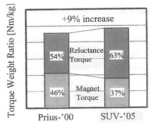
Toyota hybrid motor(s) ratio of PM torque to reluctance
torque
source -- scan from Toyota paper
Designing an
electric car
I am beginning
to understand that new electric car companies are really just acting as
prime contractors. For example in the case of the Fisker Karma --- It's
no secret they buy the gasoline engine from GM. Looking at the web site
of their battery supplier, A123, I suspect they are buying the whole battery
package from them: cells, package, cooling, thermal manegement. From
hints I found I suspect Fisker bought the drive controller from Quantum
Technology's ('Q Drive'), and of course they buy the electric motors too
(maybe from Powertec). No doubt they buy the regerative brakes and lot
of other subsystems too. Of course, the big companies do this too, buying
for example the audio systems outside, but they design their own drivetrains.
Electrics PM
=> induction
Interestingly
the one (low volume) electric on the market (Tesla Roadster) and coming
quasi-electric (GM Volt) are both using (three phase) induction
motors, not the PM/reluctance motors all the hybrids use. (In a
2007 article a CalTech long time electric car designer, Wally Rippel, said
all hybrids, with no exceptions, use PM motors.) I have read the hybrids
use PM because of its higher energy density, meaning its smaller and lighter.
While I originally found this unconvincing, when I look at the Toyota
cross-section showing the motor (and generator) tightly integrated with
the power splitter I think the smaller argument makes sense. This reason
disappears when the power splitter disappears, the motor in an electric
is probably stand alone.
The motor for an electric also needs to be x2 to x3 bigger than hybrids, and maybe you could argue (even more) reliable since the engine as a backup source of torque for emergencies is gone. Industrially large PM motors (larger than car motors) do exist, they are rather rare. Induction motors can run to higher temperatures than PM motors, because they are made of only iron and copper, there is no PM to degrade. So the tilt toward induction motors when a bigger motor is needed for electrics is probably because of some combination of thermal and/or cost advantage and less penalty for bigger and heavier.
So what type of generator is being used? I have seen no data, but it's very likely PM in hybrids. In electrics, who knows.
Neodydimium concerns
There are
three major concerns with neodydimium (used in PM motors):
* Is there
enough supply?
Neodydimium is rare earth elements and as such sources of ore are rare.
Most of it is now being used in hybrid car motors and with growth of hybrid
cars there concerns supplies will not be adequate in a few years.
* Stability
of supply.
China now controls 95% of neodydimium supplies. A company pushing an alternative
to PM motors for hybrid cars, Chorus Motors, emphasizes this point.
* High temperature
PM degradation
Chorus Motor guys claim at 100C some neodydimium magnets lose half their
field strength, but PM motors in hybrids use are better than this. The
high temperature characteristics of neodydimium based magnets have been
improved by adding 5% of dysoprosium another rare earth. Prius tackles
the thermal problem by liquid cooling the motor. The Oak Ridge report (below)
says the 2005 Prius motor tested at 21kw (cont) with 35C coolant
and 15kw (cont) with 105C coolant, a 29% roll off with temperature. The
motor has a high temperature shut down of about 170C to protect the PM
from demagnetizing.
Thermal considerations
Toyota says
in their spec that both the motor and generator are "water cooled, separate
from engine coolant". (I would be surprised if the same water water isn't
circulated to cool the inverters and battery pack.) Nope, the battery pack
is forced air cooled (? heated).
Surprisingly the Oak Ridge National Laboratory in 2005 put the Prius motor on a dynometer and extensively tested its thermal cooling system, putting on a 50 page (!) report, available online below. This was done to evaluate state of the art in vehicle motors in connection with a fuel cell R?D program that needs a 30 kw motor. (Gen III Prius motor is 'rated' at 60 kw).
http://www.ornl.gov/~webworks/cppr/y2001/rpt/122586.pdf
The high temperature degradation of PM motor is another (never talked about) consideration for the GM Volt. As the Oak Ridge report points out in a conventional hybrid, a roll off in motor performance is compensated for by cutting in the engine sooner. In the GM Volt (? a future fuel cell car) there is no engine to fall back on!
Motor speed
In Priuses
1997 to 2003 the motor had a top speed of 6,000, to 6,700 rpm, which since
these are pancake style motor with fairly large diameters, is very fast.
For the large SUV the motor size and toque (Power = Torque x speed) were
reduced by increasing the top speed to an amazing 12,400 rpm. This is not
a prototype motor, this is the top speed of production motors found in
vehicles. The paper talks about the special attention that had to be taken
in the design of the rotor, so that it could withstand the centrifugal
forces tending to make it fly apart! The Oak Ridge report shows the Prius
motor to be 4 pole-pair and is commutated with a resolver.
High speed vehicle induction motor
I found some
info on high speed induction motors for electric cars at AC Propulsion.
Alan Cocconi at AC Propulsion has been working on induction motors and
controllers for vehicles for 20 years. He did the prototype for the EV-1
and his technology is licensed by Tesla Motors. He manufacturers a 200
hp (150 kw) high speed induction motor with matching 600V IGBT controller
(AC -150) both air cooled, which he sells to people who want to convert
their vehicles to electric, and presumably it's used to in prototype vehicles
he builds for the military. A pair of them were used in a car that broke
the electric land speed record (245 mph). This system directly connects
the battery pack to the inverter, meaning the battery voltage sag at peak
power must be lived with, it is not regulated out.
I presume this motor is his design since he has patents (one of which I read) on design of low loss rotors for high speed induction motors.
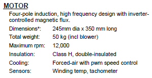 .
.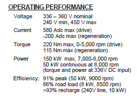
AC Propulson 200 hp, 220 nm, 12,000 rpm, air cooled
vehicle induction motor
10 in dia, 14.3 in long, 110 lbs
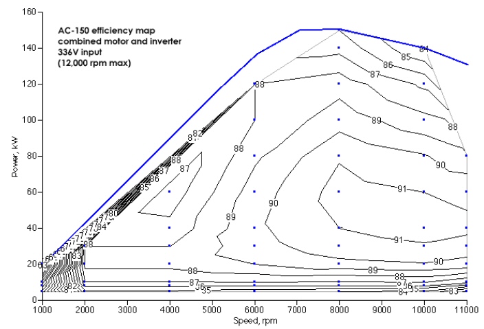
Efficiency of AC Propulson 200 hp (150 kw), 12,000
rpm vehicle induction motor
with mated 150 kw, 600V IGBT inverter (model AC-150)
Ref: 0.92 x 336V x 485 A (pk) = 150 kw
Motor speed comparisons
I am
finding there is no agreement on how to size and how fast to run the electric
motor in cars. There's a huge spread in top speeds. At the bottom end is
Fisker Karma, which I figure has a top speed of about 4,700 rpm (even though
this car has a top speed of 125 mph). At the upper end is Tesla, whose
torque vs speed curve shows the motor runs to 15,000 (or 16,000) rpm. In
between is the Ford Focue electric at 7,500 rpm, GM Volt with an electric
motor that goes to 8,000 - 9,000 rpm (check) and Leaf at 9,800 rpm.
All the electric and quasi-electric cars used fixed gearing. A couple of years ago when Tesla began the design of their first car they initially put in a two speed transmission, but it was unreliable, so it was removed for the production car. All the other companies have followed Tesla's lead and use no transmission.
Power = Torque x Speed
The basic
physics of motors is [Power = Torque x Speed]. Thus for amount of power,
which depends on weight of car, desired acceleration, and wind resistance
at top speed, the motor/controller designer has a choice:
High speed/low toque motor or Low speed/high torque motor
Motor weight depends on torque (not power)
It appears
that Tesla has chosen the former and Fisker Karma the latter. This is a
basic choice since the weight and size of a motor is pretty linear with
torque. In other words when you buy a motor pretty much you are buying
torque. If you can balance it well and figure out how to run it x2, x3,
x4 times faster, you get (for little cost) x2, x3, x4 more power for your
money and weight. Because the Fisker motors run at such low speeds, the
gearing is low, so they need a high torque rating. This makes them large,
heavy and expensive. I think each of the two motors is 11.5" in dia and
about 3 ft long. In contrast the motor for the new Tesla sedan (which weighs
maybe 20% less and a somewhat lower top speed) from pictures is only one
motor 9" in dia and about 1 ft long. A huge difference in weight, size,
and undoubtedly cost.
Gearing multiplies torqueCar maximum speed ? PM vs induction motor
The reason the smaller, relatively low toque Tesla motor can apply a lot of torque to the wheels (for good acceleration) is that its transmission ratio is high. If you can run a motor, say, twice as fast you can double the gear ratio. This allow you to cut in half the motor torque (and motor weight) without affecting the torque delivered to the wheels.
If running the motor fast saves so much weight and cost, why doesn't everyone do it? Well for one thing running 10,000 rpm and faster is high tech. I don't understand the mechanically all the tradeoffs, but it clearly takes a lot of engineering to pull this off reliably in a production vehicle. One issue clearly is balance, another is bearing wear and heating, another issue is heating of the motor iron/magnetics due to high frequency current. Tesla uses the same super high speed strategy with their first car the roadster, so they have a history with it and apparently it has proven reliable for them.
High speed torque vs speed
Another important
consideration is control of the motors at high speed and getting good torque
at higher speeds. The low speed PM motor is by far the easiest to control.
This is the low tech, safe, but expensive choice that Fisker Karma has
made. And it's probably a huge mistake, reflecting a basic weakness they
have in motor control. Everyone else is running medium high to super
high speeds. Trying to run a PM motor above its 'corner frequency' is tricky
business. It can (or could) only be reliably done to a limit extent, like
getting an extra 30% more speed.
Historically
the induction motor was tricky to control, but with modern digital controllers
implementing 'vector control' the control problem is pretty much licked,
though I suspect the controller still has some looseness over the motor
temperature range. A big advantage of an induction motor for high speed
operation is that its magnetic field is controlled by the controller, not
built into the motor as it is with a PM (permanent magnet) motor. This
allows a high speed technique called 'field weakening', where the motor
torque rolls off inversely with speed resulting in a 'constant hp region'.
This can easily extend the top speed in an induction motor by a factor
of 2 whereas a PM motor has trouble achieving 1.3.
|
|
|
|
|
|
speed mph |
|
|
|
|
|
|
|
|
|
|
|
|
|
|
|
|
|
|
|
|
|
|
(55 kw 'generator' also used as 2nd motor) |
PM |
55 |
- |
|
|
|
|
|
|
|
|
|
|
range electric (2 motors total) |
|
|
|
|
|
In early Priuses 1997 to 2000 the battery pack voltage was fed directly into the inverter. The inverter DC bus voltage would be the battery voltage, which was 274V at light load, but as power demand on a battery increases its voltage begins to sag. If fully loaded, the battery voltage would sag from 274V to near 140V. This poses a problem in motor control, because there is high voltage available (to drive the motor) at low speed and low voltage available at high speed, which is exactly the opposite of what the motor requires. As the car accelerates up (at constant toque), the motor voltage rises approx linearly with speed (starting from near zero) and the battery voltage sags (starting from 274V), and when the two voltages meet, the maximum motor torque rapidly falls off with increasing speed, or in simple terms, the motor dies.
Acceleration ? powerBoost converter
Here's the basic physics of power: Power is power, but in the electrical world it's volts x amps and in the mechanical worlds it's torque x speed.P = voltage x current electrical
P = torque x speed mechanicalDuring vehicle acceleration the torque applied to the wheels is held relatively constant, so the power rises linearly with speed. Translated into electrical terms during acceleration the motor current is constant and the motor voltage rises with speed. The inverter using the 'magic' of switching electronics is able to interchange volts ?=> amps. At the inverter input, which in early Priuses was connected directly to the battery, vehicle acceleration is seen as current increasing linearly with speed and voltage relatively constant, at least at lower speeds.
For one thing the power from the battery is now converted twice before reaching the motor. Not only is this expensive, but adding a boost converter roughly doubles the heat put out by the inverter electronics. However, a big advantage is that the boost converter 'shields' the inverter from the voltage sag of the battery. As long as the battery pack can deliver the required power, it doesn't matter (much) to the inverter how much the battery voltage sags, because the inverter sees a relatively constant voltage at its input. In other words the boost inverter decouples the battery pack from the inverter allowing better optimization. The performance advantage is that the vehicle can accelerate electrically to higher speeds.
Bus capacitors
For another
thing the low impedance of the batteries can no longer protect the transistors
from overvoltage. Now large, expensive, and not fully reliable bus capacitors
need to the output of the boost circuit to provide a stiff, high current
bus for the inverter. Traditionally aluminium bus capacitors wear out,
so I would like to know how Toyota has addressed the issue of bus capacitors
and reliability.
Why a booster
converter?
So why boost
battery voltage? Two reasons, one it improves performance. The output voltage
of the boost can be regulated. This means the sag of battery voltage
during peak power demands now does not affect (directly) how the motor
runs. The second reason is that as hp in hybrids rise, the raw battery
current gets too high to handle easily in the transistors or motor.
Say at high power the battery voltage sags to 150V, but is boosted to 650V at the inverter bus. While the boost transistor(s) have to handle the high battery current, the downstream components, inverter IGBT's and motor, can operate at current about x4 times lower (650V/150V = 4.33). A x4 boost in bus voltage above the battery, reduces the current downstream in the IGBT transistors and the motor by x4. In round numbers for the 123kw SUV this mean IGBT and motor currents are reduced from 800A range, which is very high and difficult to handle, to a much more reasonable 200A range.
IGBT transistor
modules
The
high power switching transistors that drive the motor are called IGBT (Integrated
gate bipolar transistors). They have dominated high power switching for
the last 10-20 years or so and are pretty well standardized, with family's
of different currents at 600V and 1,200V. Of course the auto market is
so large that it's possible that special voltage rated parts are used,
but looking at the nominal bus voltages in the Toyota power they are consistent
with standard 600V and 1,200V IGBT's.
600V => 1200 V IGBT's
Very likely
Toyota's gen I verhicles with 274 VDC nominal buses used 600V IGBT's, and
when the voltage booster was added in Gen II to raise the bus voltage to
500V (to 650V in gen III), the IGBT's were changed to 1,200V modules. The
motor inverter (peak) current in a gen III Prius (60 kw) is about 92A and
in the Toyota SUV (electric system is rated at 123kW) it would be about
190 A peak (190 A x 650V = 123kw). The later requires (at least) a 300A
dual IGBT 1,200V modules, which are fairly standard items, which I used
myself in designs. (It's a somewhat difficult jump to 600A single IGBT's
because it's difficult to mount the required protection capacitors.)
Fusion => 600V IGBT's
The new (2010)
Ford Fusion hybrid, on the other hand, although it has a somewhat more
powerful motor than the Prius (78 kw vs 60 kw) and a voltage booster, has
a bus voltage of only 275 V (maybe modulated up and down somewhat), so
it's very likely they are using 600V IGBT's. The 30% higher motor power
combined with the low bus voltage, less than half of Prius' 650 VDC, combine
to push the peak currents in the Fusion 600V IGBT's to about 280 A. (To
first order a 600V IGBT @ 300A with dissipate the same heat as a 1,200V
IGBT @ 150A.)
Bus capacitors
Here's a picture
of the Toyota gen III inverter opened up I found on Wikipedia. The three
big cans on the right are the bus capacitors. Big bus capacitors are needed
to stabilize the bus voltage as the chopped up motor current, which can
be 200 to 300 A, are switched into and out of it by the transistors. In
inverter design sizing these capacitors is tricky, because they are large,
relatively expensive, and unlike most electronic components they have a
finite lifetime, because they slowly dry out, and the hotter they run,
the faster they decay.
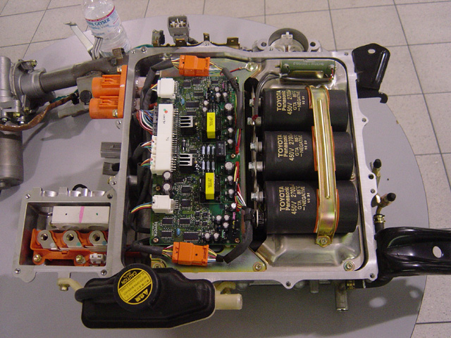
(Old) gen I Toyota inverter (bus wired to 274 VDC
battery)
Wikipedia identifies this as a Prius inverter (2000
to 2003) (NHW11)
I am surprised at how this looks. It does not look optimized in any way for high volume production (maybe it's a prototype). It looks like basically any high power inverter: same type of connectors, same array of small air cooled heat sinks, same array of small standup capacitors on PC board. The IGBT transistors would be underneath mounted on a heat sink (not visible).
The rating on the bus capacitors can be read off the side: 2,700 uf, 450 VDC, 85C. (85C is the lowest temp grade of bus capacitors) Three 450 VDC caps seems like an odd number. Don't know what the bus voltage is in gen III, but it was 650 VDC in gen II, so it's likely to be the same or higher. Therefore it takes a minimum of two 450 VDC capacitors in series to handle this voltage. With three 450 VDC capacitors in series the voltage rating is 1,350V (1,500 V surge). On first glance this seems like excessive voltage margin, and with all the caps in series they run hotter since they all have to carry the full AC current, but it might be necessary to protect the system in the event of a fault at high motor speed.
(update)
I think the
explanation of the 450 VDC bus capacitors (and look of the inverter) is
it that this is a gen I inverter (identified in Wikipedia article 'Toyota
Prius'). In gen I there was no boost converter, the battery voltage and
the inverter bus voltage were the same at 274 V (open circuit). This means
the three 450 VDC capacitors now makes sense. They are wired in parallel
and just provide local absorption of the PWM (switching) current.

Field weakening
Toyota uses
field weakening in their partial PM motor, a technique I was involved in
developing in the 1980's. This is a control technique that allows the motor
to run at reduced torque to speeds higher than is normal, speeds where
the internal voltage of the spinning magnets can be considerably higher
than the normal terminal voltage (650 V). What's tricky about this is that
if the drive 'faults' (shuts down or reboots) while the motor is running
at high speed the IGBT's and bus capacitors can potentially be exposed
to much higher voltages than normal. It might be that three 450 VDC capacitors
are used in series to prevent a failure of the bus capacitor from overvoltage
in the event of a high speed fault.
Patents
An article
in WSJ (7/1/09) says Toyota has filed for 2,000 patents on its hybrid technology,
1,000 of them related to gen III, which went on sale in May 2009. They
don't reveal how much licence revenue they earn from their patents. Ford
claims, "Our hybrids are 100% Ford-developed and engineered, (our) execution
and architecture are different", says a Ford spokeswoman. Ford recently
cross-licensed 20 or so hybrid patents with Toyota, and Ford says no money
changed hands. This would tend to confirm that Ford probably has a considerable
hybrid patent library, which is pretty surprising since they started work
in the field many years behind Toyota.
Comparing
hybrid ? non-hybrid siblings
So how much
does hybrid technology improve gas milage? A way to get a handle on this
is to compare the same car in its hybrid and non-hybrid form. Prius is
only a hybrid, but Toyota makes midsize size car in both forms and so does
Ford.
standard
hybrid
Toyota Camry
(109.3 wheelbase) -------------
------------
engine
2.4 L 169 hp
2.4 L 147 hp
weight
3,307 lbs
3,680 lbs
EPA mileage
22 city/32 highway
33 city/34 highway
sticker
22,650
26,900
standard
hybrid
Ford Fusion
(107.3 wheelbase)
------------
------------
engine
2.4 L 175 hp
2.4 L 156 hp
weight
3,342 lbs
3,720 lbs
EPA mileage
22 city/31 highway
41 city/36 highway
sticker
24,700
28,000
The hybrids are 373 lbs (Camry) and 378 lbs (Fusion ) heavier than its non-hybrid sibilings. Non-hybrids are both 22 mpg city and 32/31 highway. The hybrid Camry pushes city to 33 mpg and hybrid Fusion to an amazing 41 mpg, hybrid highway mileage is up too, 4 mpg Camry and 5 mpg Fusion. The hybrids probably drive about the same as the non-hybrids or maybe a little more peppy, they weigh 11% more, but have the equivalent of a 6 cyl vs a 4 cyl.
Toyota hybrid
technology
The newest
Prius (weight 3,042 lbs) gets 51 mph city, 48 mpg highway. 275 thousand
Priuses were sold (worldwide) in the last year. Toyota describes their
hybrid technology over the last 12 years as following into three generation.
The electrical power (called 'traction battery power' or power available
with engine off) is from a Wikipedia number. These numbers are a little
lower than I derived from the battery specs, indicating either than there
are losses and/or reserves or maybe they don't' pull maximum current from
the battery to coverup some of the roll off in current at low temperature.
gen I Prius (2000 -2003)
THS (Toyota
Hybrid System) I
no boost convert (battery => inverter)
600 V IGBT's (273V bus)
44 hp (33 kw) electrical, 1.5 L 4 cyl engine
273 V, 1.77 kwh battery (228 cells, 6.5Ah)
gen II Prius (2004 - 2008)
THS
(Toyota Hybrid System) II boost
convert (battery => boost => inverter)
1,200 V IGBT's (500 V bus)
28 hp (21 kw) electrical, 1.5 L 4 cyl engine
201V, 1.31 kwh battery (168 cells, 6.5Ah)
gen III Prius (2009 -
HSD
(Hybrid Synergy Drive)
advanced version of THS II
1,200 V IGBT's (650 V bus)
36 hp (27 kw) electrical, 1.8 L 4 cyl engine
201V, 1.31 kwh battery (168 cells, 6.5Ah)
Toyota
gen III 2010 Prius specs
I read that
in 2008 outsiders were speculating Toyota would change to lithium ion batteries
for gen III, a Toyota engineer was quoted as saying lithium batteries were
ready. The speculation in the press is that gen III has come out with standard
NiMH batteries because of fire risk with lithium ion.
motor (electric)
type
Permanent magnet AC synchronous motor
power output
60 kw (80 hp)
torque
207 nm
voltage
650 V max (indicates bus voltage is 650 VDC)
Battery
type
sealed NiMH
voltage
201.6V (201.6/1.2V = 168 cells or 28 (6 cell) modules
power output
27 kw (36 hp)
The peak electrical power spec is a little difficult to interpret. Note the motor can, and apparently does, have a higher (peak) kw rating than the battery pack. This is because (almost for sure) the generator and motor buses are common. The current into the inverter driving the motor can therefore come from both from out of the battery and (backward) out of the generator inverter. Wikipedia (Toyota Prius) lists the kw rating of the motor as 60 kw. The Toyota spec (above) shows the battery pack output rated at 27 kw.
Peak power ratings
I suspect
the 27 kw (peak) from the 28 module battery pack is right, because the
numbers fit together and look reasonable. When the motor is putting out
its peak 60kw, about half (27 kw) comes from the battery pack (via boost
converter) and about half (33 kw) come in to the common inverter bus from
the generator inverter. So we have a 60 kw motor/inverter and a 33 kw generator/inverter.
This is consistent with the Toyota cross-section diagrams which show the
generator is about half the size of the motor.
The numbers on the battery pack also look much more reasonable. As I detailed above, if the battery pack is loaded to it absolute max peak rating (matched load), the battery could deliver 36kw = (360 A x 0.5 x 201.V), but at the same time it is dissipating (as heat) 36 kw internally. By restricting the peak power out of the battery pack to 27 kw, or 75% of its maximum power capacity, the numbers are much more reasonable. At 180 A out the battery terminal voltage sags from 201.6 V to 151 V (180 A x 0.28 ohm = 50.4V). Power out is 3/4th of max capacity (180A x 151V = 27.2 kw), but the internal (heat) losses are reduced by a factor of four to 9 kw (180A x 50 V = 9kw). Now 3/4th's (27 kw/36 kw) of the battery's energy is making it to the wheels vs 50% (36 kw/72 kw) at peak capacity. Also the peak temperature rises within the cells are reduced by a factor of four!
Toyota
gen III circuit sketch
I've sketched
up (what I think is) the peak power conditions for the gen III 2010 Prius
electrical subsystem. About half (33 kw) the peak power for the motor inverter
(60 kw) comes in (from the engine) to the common bus capacitors via the
generator inverter without going through the battery. The other half (27
kw) of the motor inverter peak power is pulled from the battery pack through
the boost converter, which boosts and regulates the voltage on the bus
capacitors to 650 VDC.
Bus voltage of 650 VDC in gen III Prius was cranked up from 500 VDC in gen II (evidently the inverter in the in the 2005 Toyota SUV with its 650 VDC bus must have proven reliable!) The motor inverter current (0 to pk) is figured by dividing the peak instantaneous power out (60,000 watts) by the bus voltage (60,000W/650V = 92.3A). The 0.28 ohm battery pack ESR is figured as (10 mohm/module x 28 modules = 0.28 ohm).
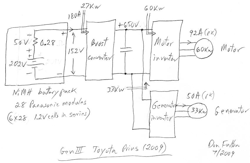
From an inverter design point of view currents of 92A not that high, there is plenty of room for expansion. The SUV rated 133 kw at 650V bus would push inverter/motor currents up to about 200 A (133kw/60 kw x 92A = 204A). 200A could be handled with 300 A dual IGBT modules, which are standard and being duals are easy to manage, meaning they are compact and easy to protect from for fast overvoltage spikes.
Whoops, I just realized something. The boost converter needs to be able to handle bidirectional power flow, which makes it more complex. Power flowing to the battery from the generator and regenerative braking (via motor and motor inverter) needs to be down converted from 650 VDC bus to the 200 V or so battery voltage.
Lexus sedan hybrids
It's maddeningly
difficult to get specs on the Lexus hybrids. As of 2010 they will have
three hybrid sedans: 4 cyl (not out yet), V6 and V8. One of the Lexus hybrids
(crossover) has a 288V battery, which looks like it may be three 288V strings
in parallel, which if the cells are the same as Prius would give it a peak
kw rating of 115 kw.
288/V/202V x 3 parallel strings x 27 kw (Prius rating) = 115 kw
| Prius | Ford
Fusion hybrid |
Hyundai
Sonata hybrid (2011) |
Lexus HS 250h
(like Camry hybrid) |
Lexus GS 450h | Lexus LS 600h | |
|
|
|
|
|
|
|
|
|
|
|
|
|
|
|
|
|
|
|
|
|
|
|
|
|
|
|
|
|
|
|
|
|
|
|
|
|
|
|
|
|
|
98 hp |
156 hp |
2.4 L 4 cyl
|
147 hp |
292 hp |
398 hp |
|
|
27 kw |
(23 kw) |
30 kw |
|
||
|
|
|
|
is gen) |
|||
|
|
|
|
|
|
|
|
Lexus LS 600h is described as having a "dual stage" variable speed transmission. With two motors (front and rear) it sounds like it probably has two sets of power splitter and motor/generators. Bottom line: The Lexus hybrid sedans are probably pretty much like the Prius except with powertrain components (mechanical and electrical) are scaled up by x2 to x4.
Prius programming bug -- 'no brakes!' (2/8/2010)
It's easy
to forget that brakes in a hybrid depend in a complex way on a computer
program within the car. Braking is a hybrid is a combination of retarding
force from the motor (regenerative brakes) plus hydraulic (electronic?)
standard brakes, which dissipates braking energy as heat in brake pads.
The program tries to use the motor/regenertive braking as much as possible
(obviously, to improve mileage) and standard brakes only a little. I presume
there must also must be a failsafe mode with hydraulic brakes able to stop
the car in a reasonable distance if the electronics have shut down or faulted
(I have seen no spec on this).
In Gen III Prius brake programing was complicated the by adding a third braking mode: anitlock brakes.
"Prius drivers have complained that the car momentarily loses the ability to brake when driven over a pothole or other uneven surface." (NYT) The car went on sale in summer, but many of the 'no brake' complaints didn't come in until customers were driving on ice in Jan. Toyota is recalling all Prius gen III hybrids to fix this.Apparently the brakes software 'bug' pops up with the antilock brake feature is being disabled and normal braking modes reengage. The scary thing is that the gen III Prius was in production for over six months (300k cars built) before this bug was found and fixed. Ford Fusion hybrid also has some sort of braking problem to be fixed by a 'software update'. Also this interesting comment attached to NYT Prius brake article:
After our Generation 2 (2009) Prius experienced a low-speed brake failure resulting in $18,000 damage, we checked the National Highway Transportation Safety Board's database for Gen 2 Prius brake complaints. We found hundreds of them. Compared to the same years of Toyota Corollas, which have traditional brakes, we found that the Prius brake failure complaint rate was over 30 times higher. For Toyota to claim, as it did yesterday, that it has had no complaints about Prius Gen 2 brakes is a huge lie. (comment 19, 2/4/2010)One poster speculated that maybe the anti-lock brakes are at fault. What anti-lock brakes do is momentarily release the brake of a wheel to keep it from breaking away and losing traction. On ice this helps stop the car. But if a road is rough and wheels start bouncing off the ground anti-lock braking engaged can interfere with your ability to stop the car.
Ford 2010 Fusion hybrid
Here's my
interpretation of the data (below) that I was able to scrounge up on the
Fusion. 2010 Ford Fusion hybrid uses a scaled up Prius architecture,
higher power and more elaborate controls, which appear to be very effective
because Fusion gas mileage is great, 8 mph better than Toyota Camry in
city. Fusion battery pack, motor, and 'power splitter' are all very similar
to Toyota Prius.
Ford has a
voltage booster (between battery and inverters), but it does not boost
to a 650 V bus like Prius. It's used (mostly) to remove voltage sag from
the 275 V battery pack holding the bus voltage for the motor at 275 V under
heavy load. The bus voltage appears to be modulated, possibly lowered at
low speeds (to improve inverter efficiency) and allowed to rise to 350
V or so if more generator power is needed? Prius uses (I think) 1,200
V IGBT (@ 92 A pk), but Ford Fusion is probably using 600 V IGBT's operated
@ 283A pk = (78kw/60kw x 650 Vbus/275V bus x 92 A).
----------------------------
Ford's Fusion
hybrid marketing phrases and news articles:
78 kw, 6,500 rpm, 275 V
(60 kw motor in Prius)
PM AC synchronous motor
73 ? kw generator
(33 kw generator in Prius)
variable-voltage converter
(probably means bus voltage is modulated
with speed ? power)
2.5 L engine, 156 hp @ 6,000 rpm (1.8 L,
134 hp @ 4,500 rpm in gen III Prius)
Atkinson, 4 cyl
1.3 kwh, 275V NiMH battery (Sanyo) (1.3 kwh, 201V NiMH battery
Prius (Panasonic)
EPA mileage: 41 city/ 36 highway, all electric: 47 mph, 2 miles distance
power-split device
Electronic Continuously Variable (e-CVT) transmission
-- The Toyota Prius, Ford Escape Hybrid use a gasoline engine and two electric motor-generators (MG1 and MG2) connected to a planetary gear set called the "Power Split Device" to deliver power to the transaxle final drive planetary gear set. (Generator and motor rating on Escape are same as Prius (65 kw motor, 28 kw generator, same 'power splitter'. The Escape hybrid technology was obtained from Toyota. Escape is apparently gen I Ford hybrid. Ford Fusion hybrid is referred to as Ford gen II hybrid.)
-- Series-parallel hybrid transaxle sourced from Aisin. Aisin site shows they make "Hybrid Electric Planetary" transmission for Ford Escape hybrid and Lexus GS450h hybrid.
-- engines valve timing, fuel delivery, and spark timing to match the power delivered through the electric motor, permitting very aggressive fuel shutdown under light loads
-- Variable voltage controller (VVC) to the Fusion hybrid that allows the voltage from the battery to be stepped up on demand. During most driving conditions when comparatively little power is needed, the lower voltage increases the efficiency of the electric drive system, while the VVC allows even greater output than the Escape when it's needed for acceleration or heavy regenerative braking."
-- Fancy blue slide says, 'Hybrid Transaxle - eCVT' lists the improvement of the Variable Voltage Converter as 130% motor, 160% generator.
NYT auto reviewer compares two mid-sized 2012 hybrids
-- Lincoln MKZ and Lexus HS (7/22/11)
The NYT reviewer
after a 1,000 mile drive in both cars finds the Ford hybrid technology
does much better in real world fuel economy than the Toyota hybrid
technology. Not only does Ford have a big EPA city 41 vs 36, but NYT finds
on highway Ford remains near its 36 mpg EPA highway rating while Toyota
falls off its 34 mpg highway rating to 28-29 in reality!
Lincoln MKZ hybrid
107.4 wheelbase
3,752 lbs (curb weight) EPA 41 city,
36 hw
Ford Fusion hybrid
107.4 wheelbase
3,720 lbs (curb weight)
Lexus HS hybrid
106.3 wheelbase
3,682 lbs (curb weight) EPA 35
city, 34 hw
"A plus for all the Ford hybrids that Ive driven, including the MKZ, is that you can drive them fairly fast (especially on the highway), and fuel economy doesnt seem to suffer greatly. The Lincolns fuel economy remained at or near the advertised 36 m.p.g. The fuel economy of the HS, true to my experience with Toyota-branded hybrids, suffered in spirited driving: the mid-30s E.P.A. promise dropped to a high-20s reality.
Certainly, Lexuss Hybrid Synergy Drive responds well to conservative techniques to save fuel gradual acceleration, coasting and highway speeds limited to less than the posted limits but so does the Ford system. Play that game with the HS and you can expect mileage in the mid-40s. When I tried the same techniques with the MKZ and Fusion Hybrids, I got as much as 52 m.p.g." (NYT 7/22/11)The MKZ Hybrid, like the Fusion Hybrid, gets power from the combination of a 2.5-liter 4, a 79-kilowatt electric motor and a nickel-metal-hydride battery pack. Total output is 191 horsepower. It also has a C.V.T. and front-wheel drive. The Lexus HS is propelled by a 2.4-liter 4-cylinder gasoline engine, a pair of 30-kilowatt electric motor-generators and a nickel-metal-hydride battery pack; total horsepower is 187. A continuously variable automatic transmission, or C.V.T., sends power to the front wheels.
The Lincoln MKZ can go about 1 mile on electricity, electric only to 25 mph or 47 mph depending on drive mode. Lincoln MKZ is really a Ford Fusion with a Lincoln nameplate. The NYT reviewer makes a big point that the 2012 hybrid and non-hybrid MKZ are the same price, but the MKZ hybrid is an overpriced Fusion hybrid available for 10k less!
Lexus hybrid
From Lexus
marketing material and random technical tidbids it's clear the Lexus hybrid
has the same hybrid architecture as Toyota and Ford (same sun/planet continuous
variable transmission). Lexus, however, mates much larger engines, a 6
cyl and even an 8 cyl, with a modest size electric system. Consider this
Lexus marketing claim for their big 8 cyl hybrid:
"The new (Lexus) 389 hp 5 L V8 when paired with the hybrid system's electrical motor, produces a combined output of 438 'horses'."This sure sounds like the V8 Lexus electrical subsytem (49 hp, 36kw) is pretty much the same as in Prius and Fusion. Gas milage is secondary to performance with Lexus, their 8 cyl hybrid has ratings of only 20 city/ 22 highway. According to Wikipedia the Lexus GS450h uses two clutches with a four shaft power splitter (ravigneux-type planetary gear) to achieve a wider speed range, up to 150 mph.
Honda hybrids
They use a
PM motor (? generator). Their NiMH battery voltage is only 158V = 132 cells
x 1.2V/cell. The batteries are made by Panasonic and Sanyo. Usable capacity
is 5 kwh, 100A peak discharge. Est 12kw = 0.75 (sag) x 158V x 100A.
Ford 2013 Fusion
hybrid --- hybrid shifts to more electric power
(11/2/12 update)
The EPA mileage
numbers for the new Ford 2013 Fusion hybrid are outstanding: 47 mpg city
and
47
mpg highway. In the past hybrids have typically had much higher gas mileage
city than highway because of energy recapture from the brakes (combined
with low wind losses), but Ford has taken a huge step forward. Its 2013
model somehow achieves very high mileage (47 mpg) both on the highway and
in the city. The NYT reviewer says, "(47/47) is a new high for a midsize
family sedan, leaving even the Toyota Camry Hybrid (at 43 city, 39 highway)
behind at the pump." I find it quite amazing that Ford's midsize hybrid
is able to get 8 mpg (47 vs 39 mpg) more than the (comparable) Toyota Camry
on the highway! Ford must have developed a lot tricks (new technology)
that I would like to know about.
I hope Ford has not cheated on its EPA testing. Hundia/Kia just this week has admitted to cheating on its EPA tests (1 to 6 mpg too high), which it then featured in its advertising.
Payback periodMy guess is the key to the good highway gas mileage has been the shift to a small engine combined with a bigger electric motor and making the combo work, and it does work. The NYT reviewer says, "The 2013 Fusion Hybrid has the most robust, transparent and enjoyable hybrid system Ive tested in a nonluxury automobile."
Even a high gas mileage car like this won't (or will barely) save enough in gas to compensate for the increase cost of the car. My Ford magazine shows the Fusion hybrid is about 5k more than the gas Fusion. Let's be generous and say the hybrid gets double the mileage of the gas model. To go 12,000 miles the gas model would burn [12,000 miles/(0.5 x 47 mpg) = 510 gal @ 4/gal = 2,040 dollars/yr]. If the hybrid really could double mileage, it would save half the gas cost or 1,020 yr for a payback period of five years (@ 12,000 miles/yr, best case).
NYT article: motor is housed within an impressively compact, seamless, continuously variable transmission. That transmission, being made in-house at a Detroit area plant, replaces a unit previously sourced from Japan. The engine has a very compression ratio of 12.3. The specs show that Ford has reduced the engire power by 15 hp (-10%) and increased the motor power by 12hp (+11%) with a combined loss of 3 hp.
Wheelbase 112.3" ! (Ford spec)
(Ford Fusion hybrid wheelbase last year was 107")
Curb weight 3,639 lb
88 kw (118 hp) @ 6,000 rpm
78 kw (106 hp), 6,500 rpm, 275 V
PM AC synchronous motor
PM AC synchronous motor
73 ? kw generator
variable-voltage converter
(probably means bus voltage is modulated
with speed ? power)
2.0 L engine, 141 hp @ 6,000 rpm
2.5 L engine, 156 hp @ 6,000 rpm
Atkinson, I-4 cyl
Atkinson, 4 cyl
188 hp total (141 hp + 47 hp = 188 hp)
191 hp
1.4 kwh lithium-ion, 35 kw (47 hp)
(1.3 kwh, 275V NiMH battery)
EPA mileage: 47 city/47 highway, all electric: 62 mph, (2 miles distance)
EPA mileage: 41 city/36 highway, all electric: 47 mph, 2 miles distance
power-split device
Electronic Continuously Variable (e-CVT) transmission
117 ft-lb motor torque
106 ft-lb
2013 Fusion has a longer 112" wheelbase
I was puzzled by
the 2013 Fusion wheelbase. On the Ford site in two places the Fusion wheelbase
as 112.3 (vs 107" from news article months earlier) with car length at
191.8" (Edmunds has the same specs.) A check of the Taurus on the
same Ford site shows it at 112.9", just a hair smaller than Fusion with
Taurus car length at 202.9" (11" longer and about 3" wider than Fusion).
The Fusion and Taurus have nearly the same wheelbase? I read the 2013 Fusion
is built on the Ford 'world-car' platform. Sure enough on the Edmonds site
a 2011 Lincoln MKZ, which Edmonds says is basically the same car as the
2011 Fusion had a wheelbase of 107.4" (car length just a hair under 190"),
so it's pretty clear that while the outside dimensions and weight of the
Fusion are pretty much unchanged, Ford has increased the wheelbase of its
midsized new cars up the wheelbase of a full size car? Sure enough a Google
search found a news article that Fusion wheelbase has gone up 5 inches,
while exterior dimension remains same. The claim, supported by reviews,
is that a longer wheelbase translates to more passenger room.
2013 C-Max -- shrunken FusionPlug-in hybrids (6/13)
Ford also has a new hybrid in 2013 with the odd name C-Max, which appears to be a shrunken (and probably cheaper) Fusion. It's almost 20" shorter than Fusion, but curiously it has exactly the same drive train and battery as the Fusion, plus it weighs almost as much (3,607 lbs) and the same EPA 47/47 mph. Its top speed is 115 mph. It also comes in a plug-in version with the battery increased from 1.4 kwh to 7.6 kwh, so on electric only it can go 20 miles and up to 85 mph. In early 2013 a plug in version of the Fusion hybrid will be available too, and a good guess is that it will sport the same 7.6 kwh battery as C-Max. (yup!)
Haven't seen any hard numbers and maybe I am missing something, but seems to me that the EV mode in these cars is quite limited. The problem is not the range, since these cars have an engine, it is that the hp in EV mode is really low. In a hybrid the electric motor and inverter are typically sized for supplemental power, and with the engine off this is all the power there is. OK if you driving at low speed, but accelerating around town or onto the highway? This explains the NYT reviewer of the Fusion Energi complaining that his little Leaf had better acceleration than heavy Fusion Energi that in EV mode only has 47 hp available vs 188 hp when operating as a hybrid with the engine though the mechanical path contributing 141 hp.
Consistent with my theory the NYT review says both the Toyota plug-in and Honda plug-in are both missing the 'EV only' switch the Fusion plug-in has, indicating it's probably something of a gimmick. Yea, you can force the Fusion to drive all electric to higher speeds, but the acceleration will be lousy, because you don't have the big motor/inverter of an all electric car, you have the small motor/inverter of a hybrid car, so the hp is not there. There's a safety aspect here too relative too, say, passing on the highway. In EV mode, what happens if you push the pedal hard, does this override the EV switch setting starting the engine to allow a safe pass? The NYT reviewer notes the Honda has a little more electric hp than the Fusion (55 vs 47).
Power flow in a plug-in hybrid
Most hybrid
cars use the 'power splitter', Toyota type, hybrid configuration. My block
diagram for this architecture with Prius (hybrid) numbers is shown near
beginning of essay. Here it is again:
It shows in the standard Prius hybrid the peak power available for acceleration is 100 kw (133 hp), 73 kw from the engine and 27 kw from the (small) hybrid battery. So in a conventional hybrid the battery is just topping up the engine power, the Prius battery power (27 kw) being about 36% of the engine power (72 kw). However, the car sports a motor/inverter of 60 kw, much larger than the 27 kw of battery power. The reason is that the (planetary) 'power splitter' in some conditions can split off as much as 33kw of the engine power, which after conversion to DC by the generator inverter adds to the 27 kw from the battery to feed the 60 kw electric motor which helps power the wheels.
Now the question is when the hybrid is configured into a plug-in hybrid by putting in a much larger battery (and almost no other physical changes) what is the power flow. The large battery has the energy for 10-20 miles of all electric driving, but the obvious problem for an electric mode is how to configure the power flow for best acceleration. A battery x3 to x5 times larger has expanded its (intrinsic) kw rating of the battery by the same ratio, so the big battery in a plug-in hybrid the battery can deliver a lot of peak power. The bottle neck is the kw rating of the motor and its inverter. Note even though the normal hybrid Prius only pulls 27 kw from its battery it has a 60 kw motor/inverter. Thus without doing anything fancy the bigger x3 to x5 plug-in battery has the kw rating to drive the 60 kw motor/inverter to its capacity.
Is (or can) the generator assist the motor in electric mode?
(update) Question is mootLooking at the hybrid block diagram I see another (possible) power path. When the engine is off and the battery alone is providing power, can the generator/inverter run as a motor help power the wheels via the power splitter assisting the main electric motor? After all the generator has about 50% the torque and power rating of the main motor, it sure would be nice to bring it into play in electric mode. Is this done? I have no idea., but on a quick look I see some issues.
Digging more deeply into plug-in hybrid specs, it looks like the question I posed here about a 2nd electrical path is moot. The EV power limit in this cars appears to be set not by the kw rating of the motor, but (for some unknown reason) the kw rating of the battery. Hence using the generator to assist the motor (even if it would work, which is unclear) offers no benefit, since the (restricted) kw from the battery is unable to drive the relatively large motor/inverter, which hybrids normally have, to anywhere near its capacity.
I would think a basic criteria in electric mode would be for the engine not to rotate, otherwise it is just wasting power. The power splitter speed formula says the generator needs to spin to bring the engine speed to zero. Since the generator likely has a speed limit of 6,800 rpm, the generator can only 'cancel' motor speed up to about 2,600 rpm. This translates into about 43% (= 2,600 rpm/6,000 rpm) of the car's maximum speed. This looks like a problem on the highway. At speeds above 48 mph (= 43% of 112 mph) the engine would begin to turn as the generator topped out in speed.
If there was a mechanical brake on the engine shaft to hold it at zero speed when the engine is off (no spark), then it would add flexibility, but I doubt normal hybrids have a brake. Even with a brake the torque contribution of the generator path would top out at 2,600 rpm at the motor, which probably means only a fraction of its nominal 33 kw rating would help with acceleration. However, it potentially could boost the low speed torque by 50%, so it could be useful. Whether this still works without a brake, I have not looked into. Maybe.
Plug-in overview
The big question
about these plug-in hybrids is how 'electric' do they drive. They must
run in electric mode to higher speeds and under more conditions than the
usual hybrid otherwise (after a test drive) no one would buy them. For
example, assuming the engine turns on to accelerate the car onto the highway,
does it then shut down for electric cruising? (rule of thumb it takes 17
hp to overcome wind resistance at 60 mph and 40 hp at 80 mph.) Clearly
much depends on the code in the car, with some added driver flexibility
in the Fusion because the driver can force it into EV mode with a switch.
Key issue here is to find out for each plug-in how much electric hp it
has and its maximum speed in electric mode.
|
|
|
|
|
|
|
|
|
|
|
|
|
|
|
|
|
|
|
|
|
|
|
|
|
|
|
|
|
|
|
|
Prius --- Usable battery energy is 3.56 kwh with Toyota speced EV range of 14 miles. Its battery specs are confusing, listed as 5.2 kwh at one point and 4.4 kwh at another, maybe because the regen battery is a separate battery. While NYT reporter said Prius had no EV switch, I read based on its test program it decided to add an EV switch for the production model.
Honda --- Unclear if this is the standard Toyota CVT power splitter configuration. It appears to have three modes. In EV mode the electric motor drives the car, there is a mode where the motor drives wheels with engine via 100 kw generator powering the motor/inverter. Unclear if there is also a direct (with some clutches?) mode for engine to mechanically drive wheels. Articles talk about the engine speed being unrelated to throttle, and this would explain why the motor is so large. Honda gives the EV range as 13 miles.
Ford says its plug-in hybrid will go about 20 miles electric.
Summary emails to engineering friends (6/13/13)
Here is how
I summarized my findings in an email to engineering friends
Email #1, puzzledFord 2013 Fusion Energi plug-in hybrid (6/11/13 update)
I've dug through the hybrid plug-in specs for Ford, Honda and Toyota and can't make any sense of it. When lots of extra cells are added to a battery in parallel, its current and power output inherently go up, but the Ford and Honda specs don't reflect this (Prius battery has no kw spec). This leads to a huge mismatch between the power rating of the battery and the electric motor.You can see this clearly in the Honda spec
http://automobiles.honda.com/accord-plug-in/specifications.aspx
It shows a 41 kw battery mated to a huge 124 kw motor/inverter. Really? Is there maybe a current limiting device, like a voltage booster, in the battery path? 41 kw is a ridiculously low rating for its big 6.7 kwh battery. The crappy little 50 lb lithium ion battery in the Honda Civic hybrid has a 20 kw rating.
Maybe these hybrids tricked out to be quasi-electrics are somewhat of a cludge. Or it could be that the low kw battery specs are just plain wrong. For example, Ford rates its battery 35 kw, yet says the car will go 85 mph in EV mode. Really? This is barely enough power to overcome wind resistance at that speed.
Prius and Accord plug-ins are only electric around town since their top EV speed is 62 mph, whereas the Fusion with a top EV speed of 85 mph should run electric on the highway for at least a few miles.
DonEmail #2, my theory (few hours later)
The (low) kw battery rating specs might be right, both Honda and Ford have it. The likely explanation, I think, is an electronic package between the battery and motor inverter: a battery voltage regulator. The voltage of the small batteries used in normal hybrids really sags when high peak current is demanded, so after the first generation Prius fixed this problem by added a voltage step-up and regulator to the battery output. I think most higher performance hybrids have this.I understand the normal Prius hybrid (not the plug-in version) well. Its motor/inverter is 60 kw powered [27 kw from battery + 33 kw from (engine powered) generator]. Hence its battery voltage regulator likely was designed with a 27 kw rating since in a normal Prius this is the max power the battery ever delivers. Put a bigger battery in this thing, but don't upgrade the regulator, and you end up with a the battery current limited to 27 kw (by the regulator) mated with a 60 kw motor/inverter. This is just the pattern I see in the Honda and Ford plug-in specs.
My guess is the EV performance in these bastard vehicles is being compromised by the existing hybrid battery voltage regulator which severely limits the available peak battery current.
Don
The NYT review of the Energi was quite favorable, however, the reviewer was unhappy that Ford (and plug-in Honda Accord) have simply taken over about half the trunk space for the battery. The EPA specs are also a little worse than the conventional Fusion hybrid (44/41/43 vs 47/47/47) probably because the car is heavier due to a few hundred pounds of battery. (Aren't EPA specs city/highway, so why is the heavier Energi highway spec so much lower? At constant highway speed with same engine the extra weight should not affect gas mileage.)
He likes the styling. It can be switched into all electric mode. However, he says in all electric mode the acceleration is not even as good as his all electric Leaf, which is what he usually drives. He says the car appears to have about twice the 'oomph' when the battery depletes and the engine starts and it becomes a normal, though slightly overweight, hybrid.
NYT review
has these Fusion Energi plug-in specs
battery
7.6 kwh (lithium ion) (35 kw power rating)
weight
3,913 lb
engine
2.0 L Atkinson, 141 hp (@ 6,000 rpm)
hp hybrid mode
188 hp = (141 hp engine + 47 hp electric motor)
hp EV mode
47 hp (my conclusion)
Cost for the plug-in battery
Fusion hybrid
28k and 32.8k loaded (Titanium model)
Fusion Energi plug-in
39.5k and 40.8k loaded (Titanium model)
Wow the cost for the extra (+6.2 kwh) battery for 10-20 miles of low power driving is an extra 8k to 11.5k! These are list prices, and apparently the plug-ins qualify for electric incentives. The NYT review speaks of the Fusion Energi plug-in after incentives being only 1k+ more than the hybrid (Titanium).
NYT 6/7/13 Fusion Energi review
http://www.nytimes.com/2013/06/09/automobiles/autoreviews/aiming-for-the-hybrids-sweet-spot.html?
Generator?
I can't find any
mention anywhere of the 'generator' in the 2013 Ford Fusion. This is the
Toyota power splitter architecture isn't it? Pretty sure it is, because
the spec says continuously variable transmission. One detailed spec lists
the motor/generator as 88 kw. Could the two motor/generators be the same
size? Unlikely, the generator is generally half the hp of the motor. In
the Toyota architecture the electric motor alone starts the car from 0
speed, and the torque to the wheels is the sum or torque from the motor
and engine. My best guess is that the generator is hidden inside the 'continuous
variable transmission' and is (still) rated at about half power of the
motor (44 kw or so).
Ford's crappy (Microsoft based) electronics (Nov 2012)
Almost every
article complains about the Ford hi-tech electronics, and there are hints
it is causing Ford to lose its reputation and sales. (Not surprisingly
some of the stuff like My Touch was co-developed with Microsoft!) The NYT
reviewer
had serious problems (stuff just not working) with a whole bunch of the
hi-tech stuff Ford fills cars with (lane changers, radar based sensors,
voice actived control panels, etc).
Here's Consumer Reports scathing view: "Why the MyFord Touch control system stinks" (Aug 2012). MyTouch replaces most knobs and switches in the car forcing you to use it. Consumer reports argues the whole concept of having to take your eyes off the road to look at a touch screen for sliders etc to do simple things like tune the radio, adjust the heater is dangerous and basically dumb with the problem compounded by poorly designed screens with too much stuff close together. (I already hate it, for the same reason I don't want electronics in my coffee maker).
http://autos.yahoo.com/news/why-the-myford-touch-control-system-stinks.html
--------------------------------------
(1/15/12 update)
Ford has revealed
features of its 2013 model Fusion (available late 2012), and it shows the
evolution of the hybrid and blending with electric cars. The NYT story
on the Jan 2012 Detroit auto show, where the 2013 Fusion was revealed says
the consensus of the industry is that hybrids are the route to the electric
car.
The 2013 Fusion will be available in three versions: gasoline engine, (upgraded) hybrid, and plug-in hybrid. The 'upgrading' of the hybrid is a shift of the power balance toward the electric drive train. Engine displacement has been reduced 20% (2.5L to 2.0L) and the hybrid battery changed over to a lithium-ion. No numbers but very likely both the hybrid battery kwh and electric motor hp are larger. This hybrid can go up to 62 mph on electric alone vs 47 mph in existing Fusion hybrids. Like the Prius it will be available with a larger (or added) lithium-ion battery charged by plug-in to give it more electric range (again no hard numbers available). Prel Ford spec shows it to have a PM motor and a continuously variable transmission, which probably means it is still using the basic Prius architecture.
Hybrid architecture
I have not
compared the Toyota/Ford/Lexus architecture other hybrid architectures
(like Honda), but as I have come to understand the Toyota architecture,
I like it a lot, it's very sweet and very flexible. I don't own a hybrid,
and am unlikely to do so for some time since I have a new car, so I can
contribute nothing from a user viewpoint. I have no real understanding
of mechanical components like gears, transmissions and power spliters,
but I do now understand the basics of the sun/planet gear set, which is
central to the Toyota/Ford/Lexus hybrid, and have written it up in detail
below.
You can't have an essay on hybrid cars without a (high level) description of the hybrid architecture, so I have dug up some good reference material. The best introductory description of the Toyota architecture I found is the first ref below. It has clear diagrams which appear to be consistent with the cross-section diagram that appears in a Toyota technical paper, so is probably correct. Another good reference is Wikiedia (Toyota Prius).
http://www.cleangreencar.co.nz/page/prius-technical-info
http://en.wikipedia.org/wiki/Toyota_Prius
Below shows the motor connected to the wheel/axle through a fixed (step down) gear ratio. According to a Slate article the Prius tops out at about 100 mph and according to a technical Toyota paper the motor speed tops out at about 6,000 rpm. Thus we can estimate the step down ratio as about 3:1 figured as follows: assume 15" dia tire (3.925 ft/rev) and 100 mph = 147 ft/sec, so wheel rpm @ 100 mph = (147 ft/sec)/(3.925 ft/rev) = 37 rev/sec (2,240 rpm). (Other references confirm: 3:1 fixed step down from motor to differential/wheels)
source -- http://www.cleangreencar.co.nz/page/prius-technical-info
Here's a cross-section of all the hybrid guts from the Toyota paper referenced above. What's jumps out is that the major components (motor, power splitter, generator, etc), which on block diagrams are drawn as separate components, are in reality all tightly integrated together. (But on reflection I guess this is what you see in cars all the time, it's what automotive engineers are good at.)
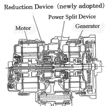
Cross-section of (high power) Toyota gen II for SUV
Engine connects top right thru generator to power
split device
3:1 step down to standard differential (then to wheels)
(in Prius cars) connects at motor shaft
motor 'Reduction Device' (2:1) is not used in Prius
cars (motor 12,000 rpm, generator 6,000 rpm)
source -- scan from 'Development of Traction Drive
Motors for the Toyota Hybrid System'
by Munehiro Kamiya, Toyota (technical paper)
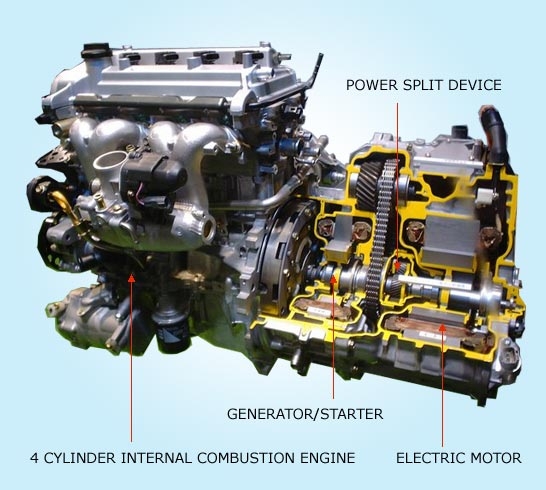
you can see in the cutaway that the generator has
roughly half the power of the motor
source -- http://www.cleangreencar.co.nz/page/prius-technical-info
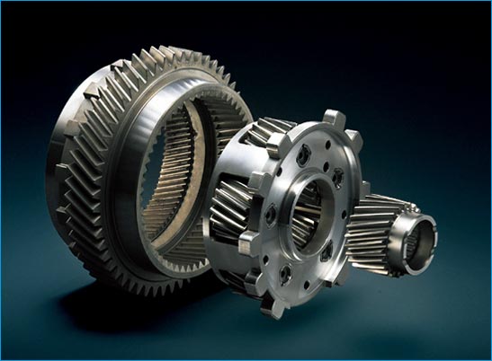
Three axes of Prius sun/planets/ring 'power splitter'
in exploded view
sun (right) --- generator
planet carrier (middle) --- engine
ring (left) --- motor/wheels
planets are five small gears (partly visible) on center
carrier
source --- http://www.cleangreencar.co.nz/page/prius-transmission
center (sun)
generator (MG1)
middle (planet carrier)
engine (ICE)
outer (ring)
motor/wheels (MG2
source -- http://www.cleangreencar.co.nz/page/prius-technical-info
How torques/power join up
As shown in
figure above, the shaft that couples to the differential/wheels is connected
to the motor on one end and the 'power splitter' at the other end. The
net torque seen by the shaft is the sum of the motor magnetic torque and
the power splitter gear torque, and since it's a rigid bar, summation of
torques is summation of power. The power than comes in via the motor is
the fraction of the engine power that was bled off into the generator and
may include power pulled from the battery pack.
Mysteries
of the 'power splitter'
A key element
in the clever Toyota/Ford/Lexus hybrid architecture is the 'power splitter'.
It's a sun/planet/ring gear set that connects together the shafts of the
engine, generator and motor. Rotation of the engine goes in and it comes
out as some combination of the speeds of the motor (wheels) and generator
according to this formula (Toyota gen I and II)
engine speed = 0.72 motor speeed + 0.28 generator speed
or
(3.6 engine speed = 2.6 motor speeed + gen speed)
What type of hybrid?
In government
reports on new CAFE (fuel efficiency) standards for cars I found the description
(below) of cars that use the Toyota type 'power splitter'. The language
is deliberately so obscure, bureaucratic and patent-like that I find it
funny. Who knew a Toyota hybrid is a 'power-split' hybrid?
Power-split hybrid (PSHEV)'Continuously Variable Transmission' (CVT)
A hybrid electric drive system that replaces the traditional transmission with a single planetary gearset and a motor/generator. This motor/generator uses the engine to either charge the battery or supply additional power to the drive motor. A second, more powerful motor/generator is permanently connected to the vehicles final drive and always turns with the wheels. The planetary gear splits engine power between the first motor/generator and the drive motor to either charge the battery or supply power to the wheels.
The trick in the Prius hybrid architecture is that the power bled off the engine by the generator is not wasted, it's fed right back into the motor/wheels because the generator and motor inverters share a common bus. The whole thing functions as an Electrically controlled Continuously Variable Transmission (eCVT). (As explained below, if the engine speed is in a sense 'too high' for the motor/wheel speed the power flow in the electrical path reverses, causing a local power loop.)
Toyota marketing shows the action of the parallel motor path acting as variable speed transmission below. Is this accurate? yes ? no Where it's not accurate is high speed highway driving. Here the variable speed transmission operates in 'overdrive' allowing the engine to run slower and more efficiently. The motor instead of adding torque to the engine path acts as a drag and actually reduces torque. (In the diagram this mean the little arrows in the motor path reverse.)

Oversimplified, in high speed 'overdrive' the little
arrows (left) reverse
How the 'power splitter' works
It's actually
pretty simple (though it took a while to realize this). The torque ratios
between the three input axes are fixed by the design of the power
splitter (diameters, # of teeth, etc). Any gear set is like a transformer
in that the golded rule is [power out = power in]. With [power = torque
x speed] and torque ratios fixed the [power in = power out] rule leads
to a constraint that the sum of the motor and generator speeds
(properly scaled) be equal to engine speed. A 'power splitter' forces a
speed
(not power!) relationship among its three shafts, as shown below.
engine power = motor power + generator power
Tengine x engine speed = Tmotor x motor speed + Tgen x gen speed
engine speed = (Tmotor/Tengine) x motor speed + (Tgen/Tengine) x gen speed
Another way to think about the 'power splitter' is that the interlocking teeth force a relationship among the three three shaft angles. You can write an equation that the three angles (properly scaled) must sum to zero, which when you take the derivative leads to the speed relationship.
Works
like a three winding transformer
A three axis
sun/planet power splitter is the mechanical analog of a three winding transformer.
A transformer sums (scaled) currents, a power splitter sums (scaled) shaft
speeds.
In a transformer the three voltages are ratioed by the design of the transformer, by the turns ratio. Power is [V x I], so the [power in = power out] rule leads to a constraint that the sum of output currents (properly scaled) be equal the input current.
n1 x i1 = n2 x i2 + n3 x i3
or
i1 = (n2/n1) x i2 + (n3/n1) x i3
Note the voltage ratio between (output) windings 2 and 3 is just the ratio of their scaling factors in the equation above, i.e. [(n2/n1)/(n3/n1) = n2/n3]. In the same way the torque ratio between the power splitter motor shaft and generator shaft is just the ratio of their scaling factors.
Toyota's
power splitter formula
Here's the
'power splitter' speed formula with Toyota's ratios.
engine speed = 0.72 x motor speed + 0.28 x gen speed (Toyota)
To better understand what this means in practice for a hybrids I worked out values over a range of vehicle speeds and put them into a table. Obviously in practice min/max rpm limits must be respected to. For the Prius the min/max rpm limits are
engine
1,000 rpm (start) to 4,500 rpm (rated torque)
generator
+/- 6,800 rpm
motor/wheels -1,500 rpm (reverse)
to 6,000 rpm (102 mph)
(wheel speed = 1/3rd motor speed fixed ratio)
|
|
Generator rpm | Engine rpm |
|
(0 mph) |
6,800 (10,800) |
1,889 (3,000) |
|
(34 mph) |
0 2,000 6,800 |
1,444 2,000 3,333 |
|
(68 mph) |
0 4,000 |
2,888 4,000 |
|
(102 mph) |
0 600 |
4,333 4,500 |
Ratio of 'power splitter' generator axis to motor axis
torque
From the Prius
speed equation we can 'read off' the design ratio of output axis' torques
(motor and generator) built into the 'power splitter' by its design (gear
ratios, etc).
(generator axis torque/motor axis torque) = 0.28/0.72 = 1/2.6 = 0.385
or
generator axis torque = 0.385 motor axis torque
(motor axis torque = 2.6 generator axis torque)
From above we can find the fraction of total power flowing through the 'power splitter' that flows in the generator axis.
Pgen/Ptotal = gen toque x gen speed/[gen toque x gen speed + mot torque x mot speed]
Ptotal (via power in = power out equation above) is also the engine power.
Pgen/Peng = 1/[1 + (mot torque x mot speed/gen toque x gen speed)]
= 1/[1 + (2.6 gen torque x mot speed/gen toque x gen speed)]
= 1/[1 + (2.6 mot speed/gen speed)]
or
= gen speed/[gen speed + 2.6 mot speed]
a) When generator
speed is low (relative to 2.6 motor speed), Pgen/Pen = [gen speed/2.6 mot
speed],
so generator power flow is proportional to generator
speed. Note, when generator speed goes negative, generator power flow goes
negative, meaning the generator is acting as a motor (looping power).
b) When motor speed is zero (vehicle stopped), Pgen/Peng = 1, meaning all the engine power flows out the generator axis.
c) When (generator speed = motor speed), Pgen/Peng = [1 (1 + 2.6)] = 0.28, or 28% of engine power is flowing out the generator through the parallel electrical path to the wheels.
Here's the table above with an added Pgen/Ptotal column.
|
|
Generator rpm | Engine rpm | Pgen/Peng |
|
(0 mph) |
6,800 (10,800) |
1,889 (3,000) |
1.00 -- |
|
(34 mph) |
0 2,000 6,800 |
1,444 2,000 3,333 |
0.00 0.28 0.57 |
|
(68 mph) |
0 4,000 |
2,888 4,000 |
0.00 0.28 |
|
(102 mph) |
0 600 |
4,333 4,500 |
0.00 0.04 |
Local power loop!
Surprisingly
power can flow in a local loop around the generator, inverters, motor,
power splitter path. Note in the table at high speeds there are entries
for zero generator speed. At these combinations of motor and engine
speed, no power is flowing in the generator path since power flow
requires
speed (P = T x speed), 100% of the engine power flows mechanically through
the power splitter to the wheels.
What happens as engine speed (at a given motor speed) increases or decreases a little from these null generator points? Clearly the generator begins to turn, positive one way and negative the other, but what about power flow? Graham Davies on his Prius page has a long write up about this.
http://prius.ecrostech.com/original/Understanding/WhatsGoingOnAsIDrive.htm
Davies explains some power loops (he doesn't use this word) when the engine rpm is low causing generator speed in the table (above) to be negative. This is the opposite of what I found in Wikipedia (in a somewhat confused article - Hybrid Synergy Drive), but Davies is probably right. Turns out this is normal driving mode. At moderate speeds on flat terrain only low power is needed to overcome wind resistance, so the engine is run at low speed for low noise and high efficiency. Under these conditions generator (MG1) rotates backwards and acts as motor. The only source of power for it in steady state is motor (MG2) acting as a generator.
As the table above shows the looping power can be considerable. For example, at 68mph reducing engine speed from 2,888 rpm to 2,000 rpm will cause 44% of the engine power to loop backwards in the electrical path with (motor (MG2) is acting as a generator and generator (MG1) acting as motor. The 44% loop back power comes from a drag load the motor (acting as a generator) imposes on the power splitter motor axis. The result is that power splitter motor axis has to put out 144% of engine power with 100% going to the wheels and 44% pulled off and circulated back into the power splitter generator axis via the parallel electrical path. Large amounts of loop back power increases electrical losses and means the teeth in the power splitter must be designed to handle the extra torque load. Very interesting.
Overdrive
Davies and
others did a lot of measurements on their Priuses and modeling, so he's
probably right. So is this looping power useful or just an annoyance? It's
useful, actually it's overdrive. Davies' argues this way.
Applying a drag force to MG1 (operating it as a generator) raises the engine speed (for a given vehicle speed) giving the car lower gear(s). The faster the generator spins positive (see table), the lower the gear ratio, the lower the engine speed, the higher the fraction of engine power flowing through the electrical path. At vehicle start (a little) power through MG1 provides the I^2R losses for high current in MG2 so it can torque the wheels hard (even without using the battery).http://prius.ecrostech.com/original/SideBars/Overdrive.htm.The table shows that the Prius will go to top speed (102 mph) with the engine nearly maxing out its rpm with the generator speed equal zero. But there's excess engine power at top vehicle speed, so it would be nice if we had overdrive, then we could lower engine speed (lowering noise and increasing efficiency). As the table shows, this is what running the generator speed negative does. Operating MG1 as a motor gives us circulating power, but it lowers the engine speed at a given vehicle speed. With the engine running slower at the same vehicle speed, of course, it's torque load rises since nearly 100% of the engine power still goes to the wheels. Now we can run the motor at (say) 3,000 rpm at 102 mph instead of 4,333 rpm with the penalty of some extra losses due to 44% power looping. We have overdrive.
It's actually rather elegant. The more power flowing forward in the parallel electrical path, the lower the gear ratio. The more power flowing backwardin the parallel electrical path (looping) the higher the gear ratio.
'Power splitter' doesn't force a power split
Proof that
the power splitter doesn't directly force power relationships is this.
Consider all electric mode with engine off and not rotating. Even though
the battery is driving the wheels directly using the motor the equation
says there must be generator speed. And there is, the generator free
wheels, it has speed but no power flow. With (engine speed =0) the
speed equation is
0 = 0.72 x motor speed + 0.28 x gen speed
gen speed = - 2.6 motor speed
Max generator speed is 6,800 rpm, so above 2,600 rpm ( = 0.39 x 6,800) motor speed, which is 44 mph, the engine has to run (or at least the shaft has to rotate)..
Cool power splitter animations
Center (sun)
is generator, middle (planet carrier) is engine, outer (ring) is motor/wheels
 .
.  .
. 
a) Engine crank, vehicle stopped
b) Drive on battery, engine stopped c) Cruising
with power from engine
directly and via generator
created by Graham Davies
source --http://prius.ecrostech.com/original/Understanding/WhatsGoingOnAsIDrive.htm
No rotation on one shaft
If one shaft
is not rotating, then the other two shafts are connected via a fixed ratio.
This is the mode during engine start with the vehicle not moving, and it's
the case in all electric mode with the engine off.
a) Generator cranks engine, vehicle stopped (3.6:1 fixed)
3,600 rpm gen = 3.6 x 1,000 rpm engine
b) Motor drives wheels, engine stopped, generator freewheels (-2.6:1 fixed)
-6,800 rpm gen = -2.6 x 2,600 rpm motor (eq to 44 mph)
(all electric speed range 0 to 44 mph)
Three shafts rotating
c) Driving with engine power (optionally battery assist)
2,000 engine rpm = 0.72 x 2,000 motor rpm + 0.28 x 2,000 gen rpm
3,000 engine rpm = 0.72 x 4,000 motor rpm + 0.28 x 400 gen rpm
4,333 engine rpm = 0.72 x 6,000 motor rpm + 0.28 x 0 gen rpm
Same axis
All
three shafts in the power splitter rotate around the "same axis". The motor
(ring) come in from one side, and (apparently) as shown in the diagram
above the engine and generator are concentric, one shaft inside the other.
The sun, planets, and ring are all geared together via teeth. No slipping.
This 'no slip' is shown below in the graphics by the gray bars always lining
up. The rotation rates of the planets themselves is unimportant since they
are not connected outside. All the matters with the planets is the rotational
motion the planets couple to their 'planet carrier' (blue middle ring).
Power splitter references
I first figured
out how the power splitter works from the excellent Prius page of engineer
Graham Davies. He created the excellent .gif graphics above.
http://prius.ecrostech.com/original/Understanding/WhatsGoingOnAsIDrive.htm
Flash animation (below) of the Prius power splitter. I got the min/max rpm limits of gen II Prius from this animation. The numbers the animation generates match the speed equation above and my table of speeds. It appears that the speed equation of the 'power splitter' did not change between Toyota gen I and gen II. I have assmed it has remained the same for gen III, but that is not confirmed.
ring/motor (wheel)
0 to 6,500 forward (0 to -1,500 reverse)
(2,000 rpm ring = 34 mph, 6,000 rpm = 102 mph)
engine
1,000 rpm (start) to 4,500 rpm (rated torque)
generator
-6,800 rpm to + 6,800 rpm
http://homepage.mac.com/inachan/prius/planet_e.html
Regerative brakes
The motor
is the key element in the regenerative brakes. When 'run backwards', it
applies a reverse torque on the wheels that brakes the vehicle and regenerates
power back to the battery. There is nothing exotic about running a motor
'backwards' to convert it into a generator (or vice versa). Inverter
controlled motors act naturally as both motors and generators, no change
of control or wiring is needed.
Motor or generatorHybrid NiMH battery packs have low ESR, so just like they can put out lots of energy quickly they can absorb lots of energy quickly. But the electrical system's hp is only a fraction of the vehicle's hp, so clearly if the car is stopped too fast the energy flow (power) recovered from the vehicles kinetic energy cannot all be absorbed. My guess, never having driven a hybrid, is that decelerations rates faster than 1/2 to a 1/3 of the vehicle's maxiumum acceleration rates will max out the electrical system, causing the excess to be dissipated as heat in the normal brakes.
If the commanded (positive) current is injected into positive EMF, which is voltage generated by rotating magnetic flux within the motor, then power flows from the battery to the wheels. It's a motor. If the commanded current is reversed, meaning (positive) current is injected into negative EMF, then power flows from the wheels to the battery. It's a generator. Simple. The same six transistors handle power flow both ways, no extra parts are needed, and torque reversals are nearly instantaneous (about a msec).
Higher power for SUV
The higher
power Toyota SUV (not the Prius car) contains a 2:1 step down coupled to
the motor. P = torque x speed and a motor is sized basically by its torque,
so the power out of a given size motor can be (ideally) doubled if it runs
twice as fast. The SUV hybrid needs over twice the electrical power of
the Prius car. This explains why Toyota has pushed the top speed of the
SUV motor 12,000 rpm and then coupled it to fixed 2:1 step down (Reduction
device) to match the 6,000 rpm rating of the power splitter.
Accleration from stop
-- The electric
motor always pulls the car away from a stand still and the petrol engine
starts to come in around the same time a non-hybrid car would change to
2nd gear. (In other words the motor (with power only? from the battery
pack) provides all the torque at low vehicles speeds (eq to 1st gear)).
Possible replacement planetary gear power splitter
(8/22/11)
Stumbled across
a 2010 paper by two Hong Kong researchers proposing a replacement for a
key element in hybrids: the planetary gear power splitter. In general terms
a planetary gear set is three port device with fixed torque ratios that
allows variable power flows by varying shaft speeds since [P = Torque x
Speed]. The new approach is to combine the motor and generator into a single
complex machine with two concentric rotors and a rotating 'magnetic gear'
in between. In total three concentric shafts!
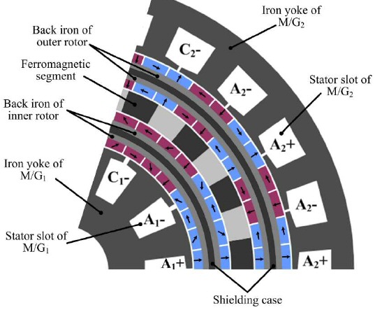
M/G1 is generator and M/G2 is x2 higher power motor
Two PM motor/generators combined with a magnetic gear
"Magnetically geared electronic continuously variable
transmission (for hybrid vehicles)"
Authors: L. Jian and K. T. Chau, EE Dept, Univ of
Hong
Kong, 2010
(source -- http://www.jpier.org/PIER/pier107/04.10062806.pdf)
The generator has its stator inside and drives the inner rotor. The x2 higher power motor has its stator outside and drives the outside rotor. Between the two rotors is what is called a 'magnetic gear', which sketches show as PMs, and it is a third rotating element. They say this, 'the modulating ring of the coaxial magnetic gear is rotatable and that that allows this machine to continuously power split and power mixing'. The designed up a half power (15 kw gen/30 kw motor) machine, and it is only about 7 inches in dia even though the speeds are low (2,500 and 900 RPM). Impressive. They argue it would be a lot lighter, more efficient, and quieter existing planetary gears sets.
Here is their Prius type sketch (same as mine, but less detail) and to the right a hybrid architecture with their new machine.
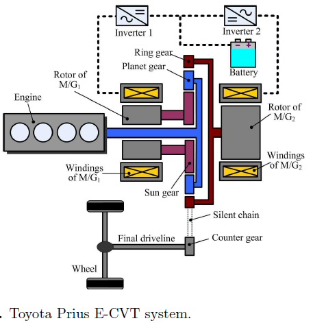 .
. 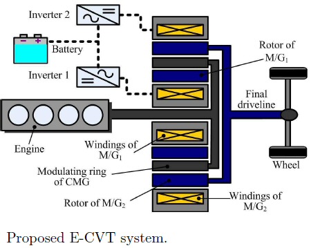
(left: Prius (same as my sketch) and (right) the Jian
and Chau three shaft machine
What is interesting is that although the new machine has three rotating shafts (as can be seen right above) only two are connected externally: magnetic gear (center) to the engine and the motor rotor (outer rotor) to the wheels. At first I was surprised by this, but looking at the sketch of the Prius (mine or above) shows it to be the same. In the Prius architecture the only power flow in/out of the generator shaft is electrical via the generator stator windings.
New Hyundai
hybrid architecture (1/31/11)
A decade or
so after Toyota introduced its power-splitter hybrid architecture, Hyundai
(Korean) will in 2011 begin selling (in USA) its first hybrid, a mid-sized
car with a new hybrid architecture, which the company describes as an "original
proprietary hybrid architecture to reduce weight and to improve highway
fuel economy". The car is designed to compete with the Toyota Camry hybrid
and Ford Fusion hybrid. It sells for 26k only 3k more than the non-hybrid
version and gets 40 mph highway and 36 mpg city. It is unusual for a (full)
hybrid in that its highway mileage is better than its city mileage.
The architecture looks simple and clean (see my sketch), so why hasn't it been used before? The explanation (from Hyundai engineers) is that the clutches until now were not good enough. The clutch here needs to repeatedly engage quickly and smoothly with the engine and motor running at high speed. Toyota in the early hybrid days tried this architecture and abandoned it because of the clutch. The key to making it work is that Hyundai has designed a new advanced electronically controlled clutch.
First look
I made the
sketch (below) from the few facts contained in a (1/30/11) NYT review article.
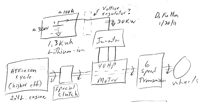
Hyundai runs the output of an 2.4L, 4 cycle atkinson cycle engine (standard car engines are otto cycle) though a advanced clutch ('secret sauce' of this architecture says the NYT), through a relatively small 40 hp electric motor, to a standard 6 speed transmission. The battery is lithium ion (instead of the NiMH usually used in hybrids) with about the same kwh rating as the Prius. Hyundai marketing makes a big point that the battery is lithium ion, but it's only real contribution is that it's a little smaller and lighter (96 lb vs 124 lb for Camry). Battery is being supplied by LG Chem and the cells are thought to be the same as in the Volt. Unlike most hybrids the motor does not start the engine. This allows the engine to be started with the clutch open.
engine + motor hp
209 hp (vs 187 hp Camry
hybrid, 191 hp Fusion hybrid)
motor hp
40 hp
engine hp
169 hp
weight
3,457 lb (263 lb lighter than Fusion
hybrid)
0 to 60 mph
9.2 sec
motor hp
41 hp (30 kw, 34?)
torque
151 ft-lb (205 Nm) (rect power peak at 1,400 rpm)
type
PM synchronous
engine + motor torque 195 ft-lb (low
speed)
battery kwh
1.4 kwh (72 cells x 3.75V/cell @ 5.3 Ahr in series)
weight
96 lb
voltage
270 VDC
drag coefficient
0.25
Combining torques
Note in this architecture
the 'combining' of the engine and motor torque (power) is trivial. No planetary
gear set here. All that's needed is to wrap the electric motor around the
engine/clutch drive shaft. Or from another point of view it's an electric
motor with a through shaft, the engine/clutch connected to one side and
the transmission to the other side. With no current in the motor windings
the motor torque is zero, the motor is effectively 'not there', there is
a direct connection of the clutch to the transmission. Put current in the
motor winding and the motor just adds its torque to the engine torque.
Simple.
The car normally starts only with the electric motor (clutch open) and the car can run to 62 mph (vs 50 mph on other hybrids) using the electric motor alone. This of course is easily achieved because the motor speed can remain low since it is on the input side of the transmission and (probably) runs at the same speed as the engine. Though the small 1.3 kwh battery only has enough power for a few minutes of all electric power at high speeds, it probably allows Hyundai to so some tricks as this hybrid boast improved highway mileage.
The 40 hp motor must be used to replace the 'missing' power and low speed torque lost from converting the engine from otto to atkinson cycle. It's clear from the sketch that anytime the engine is running and has some excess capacity that the inverter can be started up to bleed off some of the engine power to recharge the battery.
Atkinson cycle
-- An atkinson cycle
engine adjust valve timing so that the compression ratio is smaller than
the expansion ratio, or a shorter compression duration to allow the expansion
(power stroke driving the crankshaft) more time to fully run. The goal
of the modern Atkinson cycle is to allow the pressure in the combustion
chamber at the end of the power stroke to be equal to atmospheric pressure.
This converts more of the fuel energy value into mechanical work at the
expense of lower the maximum power. Due to the shorter compression stroke
the engine does not take in as much air, so for a given weight and size
it puts out less hp than an equivalent size otto cycle engine.
According to Wikpedia ('atkinson cycle') a lot of (maybe most) hybrids have their engines tuned to the atkinson cycle (besides the Hyundai Sonata) including Toyota Prius and Camry, Ford Fusion, Lexus, Mercedes and Infiniti hybrids. Use of the atkinson cycle apparently been kept secret with a 2008 article saying Toyota has just announced that the Prius uses this cycle. Supposedly the atkinson cycle (sometime called modifed otto cycle) can improv efficiency by 12-14%.
Hyundai advanced clutch
-- Hyundai
engineers suggest that the bigger advancement is its use of a clutch to
couple and decouple the engine from the transmission. According to Yang,
it's an idea that was discarded in the early years of hybrid development,
because of difficulties of engaging and disengaging the clutch fast enough
to smoothly blend engine and motor outputs.
-- "The most difficult thing to overcome was the clutch engagement system, to engage without any delay or any shocks. Ten or 15 years ago, the technology was not good enough to accurately control the engine and motor with a clutch. At that time it was not possible. That's why Toyota got away from that idea. By using new advanced electronic systems, we made it possible to engage and disengage very quickly at very high engine speeds. We revisited the old idea with new technology to make it possible." The electronics helping to reduce clutch engagement shock take into account fuel flow, spark advance and throttle position, among other things.
Chinese BYD
F3DM hybrid/electric (2/11)
A Chinese
hybrid/electric car (BYD F3DM) is scheduled to be sold in USA early
2012 and a few details are beginning to be available. Architecturally it
appears to be (basically) a Chinese Volt, but it's smaller than the Volt
with only 75 kw (total) of motor/gen compared to 165 kw (total) in the
Volt, and its engine is tiny (1 L, 3 cylinder). It began production (sort
of) in Dec 2008 almost two years before the Volt, but Wikipedia says as
of Nov 2010 only 300 cars have been sold, so it's just barely 'in production'.
It plugs in and runs all electric for 30 miles, then its (little) engine
starts and it runs as a hybrid. The engine is mechanically coupled to the
wheels (through a planetary gear set?) like in the Volt. During a hard
acceleration both motors and the engine can be used providing 168 hp (125
kw).
battery kwh
16 kwh (same as GM Volt)
battery type
100, 3.3.V lithium iron phosphate cells (330VDC bus)
active bat thermal management no
motor
50 kw (PM)
gen/motor
25 kw (PM)
engine
1 L, 3 cylinder, 68 hp (50 kw)
wheelbase
102.4 in
weight
3,439 lbs
A follow up NYT story indicates why this car did not sell in China (few sold were mostly bought by government agencies). The 2008 car is not finished, it's really a rough prototype, and needs a lot of work. One big problem is the transition from electric to hybrid. It runs differently in the two modes with a crude transition, and the hybrid mode is a horror. The NYT says when the 3 cycle engine starts "it screeches like a banshee, the steering wheel vibrates, the dashboard hums, you feel the vibration in your molars." As of now, BYD has zero dealerships in USA.
Electric car charge standard --- SAE J1772
I see conflicting numbers re: SAE J1772. Wikipedia says it is a 5 pin connector, rated 70A and 240 VAC. Others say it is 7 pin, 400 VAC, 63A. The German connector company, Mennekes, shows both for electric cars. Not sure which goes with J1772. An older IEC standard uses a five pin connector at 32A (max) 400 VAC (230 Vrms LN).Apparently the SAE J1772 (Society of Automotive Engineers) standard for plug in electric cars (SAE Electric Vehicle Conductive Charge Coupler) is still in development, though I read it has been informally agreed by a lot of (potential) electric car manufacturers. The connector is apparently (from a German connector company, Mennekes, brochure) capable of 400 VAC (230 LN) and 63A. Cables would come in different diameters with rating of 63A, 32A and 16A (smaller may use a five pin connector).
If powered from a 400 VAC line (three phase), the cable could potentially deliver 43.5 kw (3 x 230Vrms (LN) x 63Arms = 43.5 kw). Asssume pf = 1. If powered from a 230 VAC line @ 63A rms power drops to 230/400 x 43.5= 25kw.
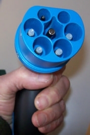
7 pin J1772 connector?, 400 VAC, 63A
(Nope, don't think so, cars have no hole for center
pin)
(update 12/14/10) Leaf connectors
Nissan Leaf
with 24 khw battery has two connectors side by side:
a) J1772 connector for Level 1, 120 VAC and Level 2, 240 VAC (1 ph?) charging
using
built in 3.3 kw charger (about 12.5A)
b) JARI DC connector designed by TEPCO for Level 3 480 VAC 50 kw (nom)
for 30 min 80% charge (about 100A). Charger is external and costs 16k!
(picture shows two large pins, so input here is DC, probably direct
to battery
or through diode to prevent external discharge of battery)
Japanese call the TEPCO, CHAdeMO (a pun), and it has been adopted by all
the Japanese car
makers (Toyota, Nissan, Mitsubishi and Subaru) for 480 VAC (Level 3) fast
charging

Nissan Leaf (24 kwh production car) dual charge ports
right: J1772 for 120/240 VAC, Level 1/2 (about 3.2
kw, 12.5A)
left: JARI DC connector designed by TEPCO for 480
VAC, Level 3 (about 50 kw, 100A)
(6/11 update) Good bet that these will be the standard
electric car plugs
 .
.
GM volt (16 kwh production car) J1772 charge port
Ford Focus electric illuminated charge port (5/11)
Kia electric fast charing port (update 10/12/14)
A late entry
in small electric cars is the Soul electric car from Kia. Based on a popular
Kia Soul model (101 in wheelbase and 2,800 lbs), they have jammed in a
27 khw battery. The combination of large battery and fairly light weight
(3,300 lb) gives it a 100 mile range. Notable, as the NYT review pointed
out, they have dual charging connectors, one of which is a fast DC charging
port. Kia dealers will all have fast charging available, and the NYT says
in 30 min 60 miles of range can be added. This is charging power [P =
0.6 x 27 kwh/0.5 hr = 32 Kw]. Kia is the only electric car, aside from
Tesla, to include DC charging as standard.
----------------------
(update 6/11/11)
Defacto standard connectors
From the photos
it's pretty clear Leaf, Volt, and Focus are all using the same 120/240
VAC charge port: five pins (three large, two small) with an insertion notch
opposite the stand alone large pin. This is the US standard 120/240 VAC
plug.
According to a Dec 2010 Leaf user site all the Japanese auto makers have all adopted the two pin (TEPCO) connector used in the Leaf for Level 3, 480 VAC, high power charging, and they think the US Energy dept is about to install the same connector in some charging fast charging stations in US. If US adopts it too, this would make it the defacto world standard for 480 VAC charging.
The 480 VAC TEPCO (CHAdeMO) connector, and associated high current wiring to the battery, apparently also exist now as an option in a tiny new all electric city car from Mitsubishi (i-MiEV). A NYT reviwer test drove the car for a week and took it to be fast charged at the only high power DC charger run in Northern CA (run by Pacific Gas and Electric). He reports delivery of 10 Kwh of charge (to its 16 kwh battery) in 15 min, which is 40 kw transfer rate! No info on losses and no info on battery voltage, but it might be 600V since 40 kw @ 300V is an awfully high 133A [40,000/300 = 133A], which reduces to 67A @ 600V.
Below is a spec for a high power 480 VAC charging 'pump' from a European company (Anker Wade, Dutch). It also uses the Tepco DC connector of the Leaf. The pump specs are:
Input
480 VAC, 3 phase, 70A
Output power
50 kw (max)
Output voltage
240 to 500 VDC
Output current
120A @ 400 VDC (48 kw)
http://akerwade.indigofiles.com/AkerWade_DC_Fast_Charge_stations_nov_8_10r.pdf
----------------------
Ford is featuring
that an optional 240 VAC charger will charge their 23 kwh (how discharged?)
Focus battery is 3-4 hours. This is possible with 240 VAC, 30A, 1 ph, which
compared to a standard 1.5 kw 120 VAC, 15A circuit would have x2 voltage
x 2x current for 6 kw capability.
Competing (older) standard?
IEC 309,
IEC 92196-1
22 kw, 400Vrms LL, three phase (230Vrms LN), 32A, five pin
3 x 32A rms x 230V rms = 22 kw (connector manuf spec)
Apparently under this standard a 250A version also exists.
Simple built-in
charger
To charge
the battery in a plug-in electric or quasi-electric from the line a charger
is needed. While theoretically the charger could be external to the car,
realistically it needs to be built-in so the vehicle can be plugged into
an available 120 or 240 VAC line. There's now a recognized standard for
plugging in a vehicle, specifying the cable and plug.
But what if the electronics and motor/generator already in the vehicle could be reconfigured to work as a charger, after all they're not doing anything when the car is being charged. If this could be done, there would be three significant gains: cheaper, lighter, more reliable. Alan Cocconi figured out and patented a couple of ways of doing this in the early 1990's. The first patent (1992) assigned to GM and the second (1994) assigned to Cocconi's own company AC Propulsion.
Alan Cocconi
Turns out
Cocconi is something of a legend in electric vehicles. A Caltech graduate,
he's been designing electric vehicle inverters and motors for 20 years.
He did the prototype for the GM famous EV-1, the first mass produced electric
vehicle. Two of his inverters and motors powered 'While
Lightning' which in 1999 set the speed record for the fastest electric
vehicle (245 mph). His company with more than 100 employees has been selling
a 200 hp inverter and mating high speed (13,000 rpm) induction motor for
15 years, and it owns a plant in China that can manufacturer 2,000 per
year. His patented charging scheme and other technology were licensed by
Tesla Motors.
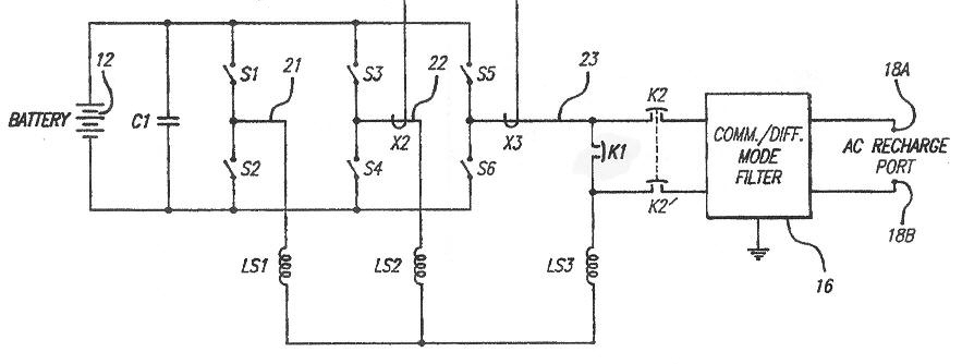
scan from patent # 5,341,075,
Combined Motor Drive and Battery Recharge System, Issued 8/23/94
Inventor: Alan Cocconi, Assigned: AC Propulsion
The trick here is to open the connection to one motor winding (with switch K1) and insert in series the (single phase) line voltage (with switches K2). When seen from the inverter, the line voltage now looks (pretty much) like the back EMF of a motor, so the normal regen mode of the inverter will now pump power from AC line voltage (120 VAC or 240 VAC, it doesn't much matter) and squirt it out as DC power into the battery at the battery voltage. Cost for the charger is pretty much just the cost of the added two high current contactors (K1, K2). No additional power electronics required!
While this scheme is neat, this is the kind of patent that early researchers get. I would argue that most good motor control engineer would come up with this basic idea in short order (motor back EMF is often modeled like the three phase line), though working out the details and robusting it would take some time.The patent shows the concept can be made to work with a three phase line too. All that's needed is to bring the neutral wires of the motor out, and the contactors insert the three phase line in the neutral connection. Note a requirement to make both of these schemes work is that the battery and all the electronics 'float' from the chassis of the car, but I think this is routinely usually done in vehicles with large battery packs for safety reasons.
Here is the efficiency AC Propulsion achieve with their 200 hp induction motor reconfigured as a charger (very likely using their patented method above). This covers the range of the standard vehicle plug-in cord and plug which maxes out at about 16 kw (240 VAC, 70A).
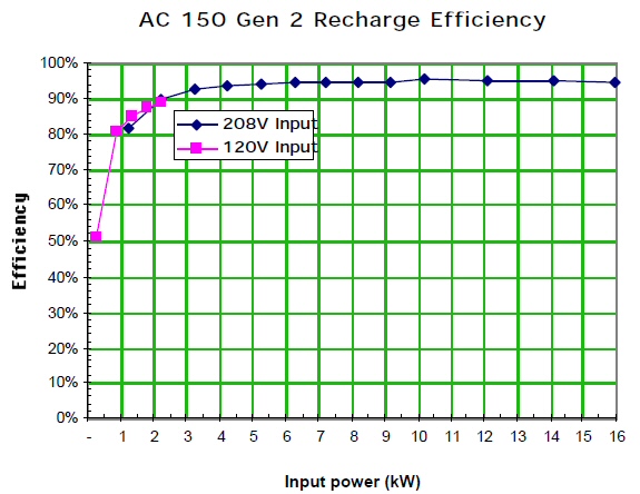
AC Propulsion AC-150 200 hp motor configured as battery
charger
Works with PM motor?
The patent
shows the recharging with an induction motor and notes it would work with
a PM motor too. Well maybe, but it's not obvious this can be made to work
properly. The issue is torque. Motors are designed to make torque when
current flows. Here the opposite is required, no torque. Clearly the charging
current can't be allowed to move the car, and it's also undesirable to
have a strong 60 hz (or 120 hz) torque that would cause the vehicle to
hum or sing while being recharged, though a creative marketing man might
be able to make this little flaw into a positive! (Curiously the issue
of torque is never mentioned in the above patent.)
Torque (in vector terms) = [current cross flux]. Induction motors will allow current flow without torque if they are controlled to keep the flux near zero. However, I'm not sure what the efficiency penalty is, because no flux is achieved by allowing cancelling currents to flow in the rotor. But in a PM motor the flux is fixed by the magnet, so figuring out how to inject currents in a PM motor (at any rotor angle) without getting a vibrating torque is not trivial and maybe not possible. If so, this might be a reason induction motors are favored over PM motors for electric cars.
In a quasi-electric there's more options, because there's also a generator. Application of this patent to the generator and its inverter to make a charger would obviate the concern about vehicle motion, and the generator would be free to rotate a little to an angle where current makes no torque.
GM Volt charger
From little
news article below it appears that the GM charger is probably not intgrated
with the inverter:
"One example (of high cost items) cited by Tony Posawatz, the director of the Chevrolet Volt program, is the on-board charger. Posawatz says the charger cost GM two or three times what it could have, because no company mass-produces a large enough charger for the Volts 16-kwh battery pack--one capable of charging from both 110- and 220- volt outlets, lasting for 10 to 15 years in harsh environment including extreme hot and cold temperatures, and enduring constant vibration." (11/2/09)-----------------------------------------------------------------------------
My interest in this was piqued when a friend send me a link to a wireless battery charger for an electric car to be sold by Delphi. You mount this 18" or so rectangular thing on the floor of your garage and attaching a thinner rectangular thing about the same size to the underside of the car, which (presumably) is hard wired into the battery charge port, so it sits pretty much above it when parked. The interesting thing to me as an EE is this product can deliver high power (3.3 kw) though a large gap. The gap is speced at 20 cm (about 8") "or more" and apparently does not need critical axial alignment to work, making parking practical.
Prof Soljacic, WiTricity
Turns out this product
is based on work done by a small team at MIT starting in 2005, led by Prof
Soljacic, who demonstrated the feasibility of resonant wireless power transfer
(with reasonable efficiency) over distances of six feet or more. I vaguely
remembered reading about this when it hit the front page of the newspaper
five years ago, but I had heard nothing about it since. Soljacic formed
a company, WiTricity, to commercialize the technology, and as far as I
can tell, this is the first actual product to come out of this work. I
was always interested in how they had done this, so when I found they had
patents, I dug them out and read them (75 pages worth of patents!)
#7,741,734 and #7,825,543. Soljacic is a physicist (two BS's from MIT in
physics and EE) working at the Research Laboratory of Electronics and seems
to work mostly on non-linear optics.
Included in the links below are a couple of papers with much of the same info as in the patents. One paper has two worked out example where 10 watts is delivered to a lap top with a D/r =5. The efficiency for what they call a dielectric disk (not sure what this is or looks like) is 51% and for a capacitively tuned coil its 61%. I suspect the dielectric disk runs at a higher frequency because most of the ten watts of so of loss is 8.3 watts of radiated power. The losses in the higher efficiency (61%) capacitively loaded coil on the other hand are mostly in the coils, with radiated power very low at (1/2 w). So coils have less radiated power and higher efficiency, but things run hotter.
http://www.witricity.com/pages/invention.html
http://www.mit.edu/~soljacic/wireless-power_AoP.pdf
Tuned resonant coils
The key to getting
power to transfer over large distances, and without critical axial alignment,
is to use two resonant (high Q) coils tuned to the same frequency.
When two coils are far apart, the overlap of their magnetic fields is quite
small, even with coils of the same diameter on axis, no more than
a few percent or maybe less than 1%. When transformers are built, the materials
and geometry are chosen to overlap as much of the fields of the coils as
possible, and usually 90 to 95% coupling is achieved.
So the obvious question is how can power transfer work across such large gaps? The trick it turns out is to use resonant coils tuned to the same frequency. Even though there may be only, say, 1% flux coupling between the coils the analysis of the MIT team showed that when power is extracted from the receiving coil it is replaced (next cycle?) by power from the source soil.
My picture/circuit modelThe key is to making the power transfer practical is to keep down the losses, hence high Q, which means not only low ohmic and dielectric losses in the coils and adjacent materials, but also low radiation losses. In other words don't build an antenna. At this point I had no clue as to what frequency range they operated at. All I found in the press material and online was that that the coupling was via the 'near' field, but the patents provided the answers.
They provide no 'picture' of how this happens, but my guess is this: The near magnetic field probably where all the inductive (non-disappative) energy of the coil is stored. Each cycle it builds up and then winds down as the energy shifts to the electric field in the capacitor. Since this near field is in air (unguided by high u magnetic materials) it spreads out, and the receiving coil in its far reaches intercepts only a tiny fraction of it.With the receiving coil in place absorbing power (it will create a current that tends locally to cancel the incoming field) the voltage in the driving coil is slightly affected, because the 'back EMF, i.e. the d(flux)/dt, is slightly affected. So in circuit terms a resistor will appear in the primary circuit. And even though the reactive energy may be x100 the resistive energy lost per cycle, if the Q can be kept high (say 500 -1000) then most (or much) of the real power flowing into the primary coil ends up in the receiving coil.
Turns out that resonant coupling between coils has long been known to occur, and it had in years past occasionally been used when low power was needed remotely, like to power something in the human body or human ear, but apparently no one had really studied it seriously, until the MIT people, to see if it had the potential to wireless charge mobile devices. In engineering school the near field is shown in the text books, but is otherwise ignored. Transformers operate with very tight coupling, and antennas work in the far field. The far field is a radiated field, and here the laws of electromagnetics require that the local electrical and magnetic energy in space be equal. But this is not the case in the near field, the electric field can be much larger than the magnetic field or vice versa. It all depends on how the coils are build and tuned.
High vs low impedance coils
A parallel LC coil
will yield a high impedance, hence high voltage (low current) at resonance,
so its near field is dominated by the electric field. Turns out this is
not so good for humans nearby to be exposed to as our watery bodies absorb
a lot of this energy (as heat). If the coil is built as a series LC, then
it will have a low impedance at resonance, hence high current (low voltage)
at resonance, so its near field is dominated by the magnetic field. The
human body is nearly immune to the magnetic field, so this is the preferred
way of doing the coupling. Unfortunately, it turns out that a switch from
electric to magnetic coupling with coils of the same diameter cuts the
efficiency about in half, from something like 40% to 20% according to their
initial studies and demo in 2006.
Note, I find the efficiency claims in their papers confusing. High numbers (> 50%), apparently the result of theoretical studies, will be followed later in the paper by low numbers. The measured efficiency in their initial 2 meter, 60 watt demo was only 15%.With a capacitively tuned wire coil they say the electric field is mostly inside the capacitor and the near field is mostly magnetic. To deliver a few watts of power they say the near field magnetic strength is about 1 gauss (magnetic field of earth is about half gauss).
What frequency/wavelength?
But what frequencies
are they using. Microwave? No it turns out the frequencies are quite low,
17 Mhz to 380 Mhz for coils 1 to 30 cm in radius, the lower frequencies
used with the bigger coils, it pretty much scales linearly. Their demo
transmitted 60 watts over 2 meters with 30 cm (radius) coils powered at
17 Mhz (sinewave). The wavelength of 17 Mhz is 17.6 meters = [3 x 10^8/1.7
x 10^7]. In other words both the coil radius and transmit distance are
much smaller than one wavelength. In the demo the ratio of wavelength to
coil radius is about 60:1. The patent analysis finds high Q's can be obtained
with transmit distance (D) to coil radius (r) ratios of 3 to 10. D/r ratio
in the demo is about to 6.7.
Demo
To get 60
watts into a 60 watt light bulb the input power to their (colpits) oscillator
was about 400 watts. They pretended not to know the efficiency of the oscillator!
The overall efficiency was about 15% to transmit power 2m with a theoretical
efficiency for the wireless transfer of 40 - 50%. Unfortunately the 40%
efficiency was for a thick open coil (high Z) whereas a more practical
thinner wound coil (low Z) gave about half the efficiency (20%). They built
and tested both types of coils (same 30 cm radius), but the news stories
of course featured the less practical deep coil. If you look closely at
photos, you can see a smaller light bulb (30 watt?) was used with the thin
coil.

MIT's 2007 demo powering 60 watt light bulb (Prof
Soljacic is in 2nd row, striped shirt)
(2 meter gap, 30 cm radius 'thick' transmit and receive
coils, freq = ??)
These are self resonance air coils, meaning the capacitance
is between turns
(source -- http://www.mit.edu/~soljacic/MIT_WiTricity_Press_Release.pdf)
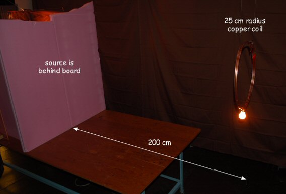
MIT wound 'thin' coil demo
(2 meter gap, slightly smaller radius coil, 25 cm)
It is likely this is tuned with a capacitor, but it is
not visible.
No info on power delivered, but this looks like a smaller
light bulb
(source -- http://www.sciencemag.org/content/suppl/2007/06/08/1143254.DC1/Kurs.SOM.pdf)
Wireless car charger
The $64 question
on the wireless 3.3 kw electric car charger is its efficiency. Curiously,
suspiciously, it is not given. But looking at it, it does not look capable
of dissipating a 1 kw, so I suspect the efficiency must be pretty high
(> 70-80%) to make it practical. It is operating with a gap (8") that is
equal to or less than the radius, and this case was not discussed in the
early papers and patents where lower end D/r was usually 3.
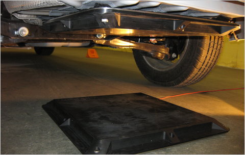
(source -- http://wheels.blogs.nytimes.com/2010/11/02/delphi-and-witricity-developing-wireless-electric-car-charger/)
In a Nov 2010 NYT article about the partnership between WiTricity and Delphi the marketing director of WiTricity is quoted as saying the efficiency will be 95%! This will be spectacular if it can be achieved. (My guess is they will have a hard time reaching 90%.) As of now, the Delphi web site says "in development, not available". One glaring problem here is keeping the resonance of the two coils aligned, since the receiving coil is mounted on a metal car, which will affect its inductance a lot! (There might also be eddy current loses in the car metal.) Will they be forced into active adjustment? More likely they are hoping this might one day be a factory installed option, which would allow the receiving coil to be custom engineered for that particular model.
NYT quotes
lots of people saying "who needs it?", but the first time someone drives
off with his car still plugged in (lock out?) his opinion will change.
Long term something like this may make sense, but it has got to be efficient
and not too expensive.
-----------------------------------------------------------------------------
MPGe EPA standard
EPA has adopted
for electric range a milage standard called MPGe, miles per gallon equivalent.
Here is the EPA definition:
The E.P.A. offers this definition, which seems clear
and reasonable to me.
MPGe explanationQuasi-electric Volt has a MPGe rating of 93 and the much heavier Fisker Karma 52. Check: Volt can go about 35 miles electric says EPA using (I presume) 10.6 (?) kwh of its 16 kwh battery. So the MPGe would be
The mpg-equivalent metric expresses the energy consumption of a nongasoline vehicle in terms of how many miles the vehicle could go on gasoline if it used the same amount of gasoline energy as it used of the nongasoline fuel energy.For example, a gallon of gasoline has the energy equivalent of 33.7 kilowatt-hours of electricity. An E.V. (electric vehicle) that uses 33.7 kilowatt-hours to drive 100 miles will use the energy equivalent of one gallon of gasoline, and therefore would have an MPGe of 100 miles per gallon of gasoline equivalent.
(33.7 kwh gasoline eq/10.6 kwh used) x 35 miles = 111 MPGe
vs 93 MPGe EPA rating (something is off)
To explain the difference it is necessary to reduce the Volt's electric range to 29 miles for 10.6 kwh usage.
Wind resistance hp
"As the Prius
reaches motorway speeds, the Prius will normally be driving solely on the
petrol engine." (The engine must initially put out addtional power to recharge
the battery, replacing the charge used to accelerate.) The engine is rated
98 hp (gen III) and 76 hp (gen II), so obviously less hp than this is required
to overcome air resistance at highway speeds. Wind resistance goes as speed
squared and power goes as speed x load, so the power to overcome wind resistance
goes as the cube of speed, or 338% more power at 90 mph than 60 mph. The
Prius max speed is reportedly about 100 mph, so working backward I get
that it must only take about 16 hp to overcome wind resistance at 60 mph.
(76 hp gen II/(100 mph/60 mhp)^3 = 76 hp/4.6 = 16.4 hp).
Check --- Wikipedia says car wind resistance runs 10 hp @ 50 mph, 80 hp @ 100 mph, which calculates to 17 hp at 60 mph, almost exactly the 16 hp I estimated from Toyota numbers.
Misleading block diagrams?
Many of the
simple block diagrams I have found of hybrids are too simplified to be
useful, and some seem just wrong. For example, I often see the generator
drawn to the side of the power splitter (below), whereas the cross-section
diagram from Toyota shows it clearly in line between the engine and the
power splitter.
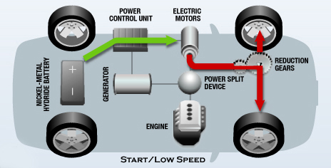
Misleading? Notice this show the generator to the
side of power splitter,
but cross-section diagrams show generator inline betwen
the engine and power splitter
source -- http://www.global-greenhouse-warming.com/hybrid-electric-vehicle.html
(update)
Well, having
tried to sketch it myself, I see the difficulty. Physically the generator
is inline between the engine and the power splitter as shown in the figure
(way above) showing concentric shafts. But if you start with the physical
configuration its difficult to show functionality. Thus showing the power
splitter with a side (non-axial) output, while physically misleading, I
now think is not really wrong because it does correctly show functionality
and is much easier to draw and read.
Power doubly converted?
Some published
diagrams show the engine sometimes powers the wheels partially via the
generator/motor path. I initially suspected this was wrong. I mean, why
convert engine power to electrical power and then back again to mechanical
power, but the Prius specs do seem to show this. My own circuit diagram
of gen III Prius shows 33 kw of 60 kw of the motor power comes into the
motor inverter bus from the generator.
I don't really understand why 33 kw of power would be doubly converted. Why not pass it directly from the engine to the wheels through the power splitter? Maybe it's for flexibility of control or maybe reductions in cost/size of the power splitter. Power flow though the generator/motor path is very easily and quickly controlled electrically, so maybe this is the reason. The efficiency penalty for doubly converting 33 kw is not too large since inverter/motor efficiencies generally run in the 90% to 95% range.
(update)
Obviously
when I wrote above paragraphs I had no clue as to how the architecture
of the Prius hybrid really worked. I've left it in just as a guidepost
as to how I come to understand things. I now understand that:
The two parallel power paths from the engine to the wheel provided by the three axis sun/planet/ring gear set ('power splitter') and two coupled inverters (for motor and generator) functions as a continuously variable transmission between engine and wheels controlled by adjusting current flow in the two inverters. The DC bus of the two inverters is connected direct to the battery or via a battery voltage booster. This provides bidirectional power flow from battery to the wheels (via the motor), providing all electric driving and regenerative braking, and bidirectional power flow from battery to the engine (via the generator), providing engine start and battery recharge.My personal contributions to hybrid/electric technologyAnd since all the inter-connections are in place all the time and all the elements in the system (battery, motor ? gen, inverters, sun/planet gears, engine) allow bidirectional energy flow, the system is very flexible. The battery can be charged or the battery can assist driving the wheels while at the same time the engine drives the wheels though the variable speed transmission.
Field weakened PM (permanent magnet) motor technology
In the early
1980's PM motors were the standard motor for servos, as they are today,
because they are easy to control, very efficient, and have a convenient
rectangular T vs Speed curve. A servo PM motor can be run at any speed
up to 'base speed', defined as the speed where the back EMF (from the spinning
magnet) equaled the inverter bus voltage, but above that speed the motor
torque rapidly dropped away to zero.
For servo applications the 'base speed' speed limit of a PM motor was not a problem, but there are other applications, like vehicles, where a wider speed range with reduced torque at higher speed is needed. The goal in high speed torque is a 'constant hp' curve where torque falls off slowly (as 1/speed). You can do this in induction motors by lowering the component of current that sets the magnet flux level in the motor. but in PM motors the flux level is fixed by the magnet.
Operating the PM motor above base speed was thought at the time to be impossible. PM motors just refused to accept much current above base speed, because (net) voltage needed to ramp up current in the motors' inductance gets squeezed to zero between the back EMF and bus voltage, so the torque dies. There appeared to be little that could be done about this because voltage from a changing magnetic field (like a spinning magnet) is a law of nature, it's built into Maxwell's equations, and a motor's inductance is basic to it creating torque.
But there is a way to run a PM motor x2 (maybe x3) times higher than it's base speed and my boss (Bill Curtiss) and I figured it out.
IMEC company lore
As R?D engineers for a motor control consulting company (IMEC), we flew out to Wisconsin in 1981 (or 1982) to describe our new PM control idea to the large electrial company that was funding us (Allen Bradley). I was up at the black board drawing out the vector diagrams of how to do it (the concept was really pretty simple), but the Phd motor control expert that we were trying to convince (Dr. Nondal) was skeptical. "What about the motor's sub-transient impedance", he asked us. Well neither I or my boss had ever heard of the 'sub-transient impedance' and so we sheepishly had to ask ask what it was and still didn't have a clue after hearing Dr. Nondal's explanation.
Sub-transient impedanceNeedless to say we didn't convince the experts that day that the concept was sound, but it was sound. We tried it, and it worked. This concept is now well understood for PM motor control and it's probably being used, at least to some extent, in PM motors in hybrid vehicles, since a wide speed range is needed.
It turns out, I found out later, that large conventional line operated synchronous motors, which are a somewhat rare and exotic type of motor that had been around for nearly a century, have built into them shorted windings to provide damping, because otherwise these motors oscillate around the phase of the line as they rotate. The 'sub-transient' impedance referred to the fact that these shorted coils could be viewed as causing the impedance of the motor to be time varying. Of course, the motor we were discussing was a servo type PM motor, which has no such shorted coils, so the 'sub-transient impedance- question was out of left field and not relevant to what we were proposing.
Our PM control idea
Our idea was to
control PM motor currents in such a way that the back EMF is partially
cancelled using the motor inductance. We proposed adding a (non torque
producing) quadrature current term in PM motors. Since voltage leads current
by 90 degrees in an inductor, this creates a voltage across the motor inductance
that is 180 degrees out of phase with the back EMF. It's a cancelling
term that makes the motor's back EMF, as viewed from the outside,
look smaller than it really is. Above base speed the internal motor
back EMF voltage from the spinning magnet can be much higher than the bus
voltage, yet with proper control law for motor currents the voltage at
the motor terminals, which is the sum of back EMF and inductive
voltages (plus IR voltage), can be held to less than the bus voltage
allowing the motor to be well controlled.
Fly in ointment?
There is a
fly in the ointment though. A nagging concern has always been what happens
at high speed if the inverter has a fault, i.e. it suddenly shuts down
for some reason. There is still high voltage inside the rapidly spinning
motor, but the cancelling voltage now disappears, so there is risk of inverter
damage due to over voltage. While this is speculation, this robustness
concern may explain why the Toyota's hybrid motors, which are marketed
as PM synchronous motors, are revealed in the technical literature to be
combo PM/reluctance motors, the reluctance torque allowing the PM flux
levels to be substantially reduced.
High performance induction motor technology
In my essay
on Tesla's induction motor (below) I describe in some detail my contributions
to induction motor control theory.
http://twinkle_toes_engineering.home.comcast.net/induction_motor.htm
Brief summary of my contribution to high performance
induction motor control
For several
years in the late 1970's all attempts by researchers at getting servo-like
performance from the induction motor failed. A step of torque (really
a fast ramp) would be requested, but the motor, if it made the torque step
at all, would then 'ring' the torque for a half second or so. No one could
figure out how to stop the ringing.
The failure to tame the rotor time constant was indicative of the fact that no one at the time, not even the experts, 'really' understood how the induction motor worked. At least they didn't understand it dynamically. The induction motor, while complicated, had long been written up in the motor text books, and the text books were accurate as long as things didn't change too fast. Think how remarkable this is. The world's most common motor and almost a century since its invention, and no one really understands how it works!Here is where my work comes in.... I solved the ring problem. Yes, I did, the patent record confirms it. I contributed to improved understanding of the induction motor dynamically, and my contribution laid the groundwork for the standard ('vector') induction motor controller of today. I worked on induction motors first at Draper Laboratory (formerly MIT Instrumentation Laboratory), which was a large, mostly government funded research and development laboratory in Cambridge MA. They filed for a patent on my induction motor breakthrough in 1980 (Title: Induction Motor Controller with Rapid Torque Response) with me as sole inventor, and in 1982 the patent was granted. (US patent 4,348,627).
I remember how the break through happened. I was in the quiet Draper library reading a colleague's draft MIT's Master Thesis on another aspect of induction motor control, when it suddenly occurred to me that maybe the phase of the motor currents were not being properly controlled, i.e. there was a missing phase term in the equations. I sketched what I thought the phase term should be (surprise, it is related to the rotor time constant) and we plugged it into a computer induction motor model which we already had that displayed the torque ringing. When the phase term was added, the ringing completely disappeared. So within an hour it was pretty clear that I had guessed right, we had found the key to getting servo like performance from an induction motor!Two years later I left Draper Lab with three other Draper people to form a new start up company (IMEC Corp) to work on induction motor controls and other cutting edge work in motor control. There Robert Comstock and I used our recently won understanding of induction motors to make one of the first induction motor controllers. We developed, prototyped, and patented a complete high performance induction servo controller in 1982. (US Patent 4,484,126, filed 1982, issued 1984). I presented a paper at an engineering conference showing my new model of the induction motor, and Machine Design, a well known engineering magazine, picked up the conference paper and republished it in their magazine as a feature article.In turns out (in hindsight) that a key stumbling block to understanding the induction motor had been that the textbooks for nearly a century had said induction motors were 'asynchronous' motors (often the chapter title), meaning motors that are phase insensitive. That's wrong! For times less than the rotor time constant (few tens of a second) induction motors are synchronous motors and the phase of the currents (relative to the rotor angle) needs to be controlled.
These induction motor control concepts are now built into modern induction control theory, often called vector control or field control, which will be used in any (electric) vehicle powered by induction motor(s), like the Tesla Motors Roadster and the coming GM Volt.
Battery cost
Big buck have
been poured into battery development for vehicles in USA for 20 years.
Progess shall we say has been slow...
"In 1991 the Advanced Battery Consortium was founded and set a near-term target for developing a battery that would cost $150 per kilowatt-hour of storage. (A kilowatt-hour sells for about a dime and will move a car three or four miles.) Eighteen years later, prices are in the range of $750 to $1,000". (NYT 7/27/09)Oh yea!"G.M. would not disclose the price of the (GM Volt) battery pack" (NYT 7/27/09)
Government
is now planning to spend 2 billon!! on battery development beginning summer
09. Every company that makes batteries is going to be swimming in money,
numbers being thrown around are 150 million per company!
=================================================================
Misc
In a Prius
forum someone asked how the engine can be started there's not enough charge
in the main NiMH battery. The answer was that the 12 V lead acid battery
through MG1 (generator) starts the engine. Is this right? Is it a backup
mode? Seems to be to make this work would require an extra step up converter
because the generator has high voltage winding.
Here is a good detailed tutorial that explains the main NiMH battery is used to start the motor.
http://prius.ecrostech.com/original/Understanding/WhatsGoingOnAsIDrive.htm
Tesla misc
Owner takes
his Tesla Roadster to a 2.5 mile road track. In only 3 to 4 miles(!) of
hard driving the power of his inverter is dialed back as its hot warning
light comes on, then his motor hot warning light comes on too.
"Typically, the PEM (Power Electronic Modules, aka, inverter) hot warning would come on in 1 to 1.5 laps, then the motor hot warning would come on in several more laps with associated power reductions. As an example, on the highway straight away, with a fresh cool car, I could get 110 MPH, but with reduced power, all I could get was 90 to 95 MPH."Forum guys says PEM is air cooled. Big mistake! They will be moving to water cooling in future cars.
Tesla has a
17 kw charger. This gives a charging time of 3.5hr (for about 50kwh) if
17kw is available
from 240 VAC 17kw is about 68A. Guy at test
track recharged at @ 40A from 240 VAC RV outlet.
Tesla has run their induction motor on the dyno to 18,000 - 20,000 rpm. Car limits is 13,000 to 14,000 rpm.
Tesla patent applications
20070284953
motor rotor
20070009787
cooling batteries
20070218353
battery fire suppresion
20070188147
fuse links for batteries
Tesla Motors' Stealth Bloodbath - After raising over $100M, Tesla Motors Inc. has fired over thirty people -- nearly the entire team. Nagging transmission problems were partly to blame for the meltdown. (TeslaFounders; Jan. 10, 2008)
Powertrain
1.5 redesign (to eliminate 2 speed transmission)
"The revised
PEM has new transistors (higher I rating) that help improve the overall
efficiency, allowing more power with less heat generation."
"The more
substantial changes are in the motor. The terminal connectors have been
redesigned and the high voltage cables that connect the motor to the PEM
have been switched from copper clad aluminum to pure copper. The locations
with the highest resistance were attacked directly allowing more current
flow without increasing temperatures. The result is 33 percent more torque
at the thermal limit than the existing motors."
"I can't keep the Tesla drive train versions straight. Anyone have a program? As best as I can remember it, first it was a two-speed transmission from vendor 1. Failed. Then a two-speed from vendor 2. Failed. Two-speed from vendors 3 and 4. Failed. Single-speed design, let's call that 5. Failed. Now we have yet another design."
Just to make
the record clear it goes like this:
1. Two speed from vendor 1: failed
2. Two speed from vendor 2: failed
3. Planned to try a two speed from vendor 3 ? 4.
4. Found better plan during development in Whitestar:
go with a single speed while increasing power, so plans for two-speed dropped.
5. Production cars 2-40 gets/will get 1 speed (AKA the
"temporary transmission") which works in every way on target (durability
and etc), except 0-60 is 5.7 seconds instead of 4 seconds. (Production
car #1, AKA Elon Musk's car, has a 2 speed)
6. Production cars starting with #41 is getting the single
speed "drive train 1.5" described in this article, which does get 0-60
in 4 seconds.
** "PEM which can now do a 640A current limit on its input as well as a new and higher 850 amp limit on its output are all good incremental upgrades. We now multiply that by the latest motor current increase, 850A/640A (May 2008)
** "Ver. 1.5 adds a current boosting voltage reducing circuit for low speed operations to improve low speed torque." Forum post (not sure what this means.)
One possibility is that at low speed they are using contactors to reconfigure the battery. Putting two five sections in parallel would half the voltage and double the available battery current. It would also make the IGBT's happier by cutting switching loss in half when they conduct maxium current. The negative to this is there's a 'switch point' where torque is lost as the contacts throw and battery reconfigures. Is there an effective gear switch in their one speed transmission? Or, maybe he's just talking about voltage sag
"Eberhard (former CEO of Tesla) wrote a well publicized and needless (a fix was already in progress) negative blog piece regarding the battery coolant pump soon after receiving the car (production car #3).
Severinsky 'Hybrid Electric Vehicle' patent, US Patent
5,343,970 (filed 1992, issued 9/6/94)
Alex Severinsky,
a US engineering professor, entrepreneur and immigrant from Russia, won
a hybrid (architecture) patent infringement case against Toyota. After
many years of legal battles both Ford and Toyota settled with him in 2010.
He claims to be the inventor of the Toyota architecture. Is he? Here is
his page one figure from the patent in question (US Patent 5,343,970).
Alex Severinsky hybrid vehicle architecture (circa
1992)
34 (top) are the vehicle wheels
Note has only one motor/inverter
(US Patent 5,343,970, figure 1)
It does feature a three shaft torque sharing device and no transmission. His torque sharing device is not described as a planetary gear structure, nor did I see the words 'infinitely variable transmission' used in the text. Note that the computer is shown directly controlling the torque sharer.
While his architecture does have some resemblance to the Toyota architecture, it is certainly not the same. For one thing he has only a single inverter (connected to the motor) and no generator. When highway driving, the computer controls the torque sharer (via locks and pins) such that some of the torque is split off to run the motor/inverter backwards to charge the battery. Severinsky has the motor and engine on two shafts of the torque sharer with the wheels connected to the 3rd shaft. This is not how Toyota does it.
Toyota architecture is less obvious and much more subtle. The wheels and motor share one shaft of the power splitter and the generator/inverter are on a 2nd shaft. By coupling the DC links of the two inverters together a dual power path from engine to wheels is created that functions as an infinitely variable transmission (including overdrive). The Toyota power splitter (I am pretty sure) is a purely mechanical device. All the torque and power sharing control is provided by drive currents of the two inverters. There is nothing like this in Severinsky patent.
So does Severinsky deserve credit as the 'inventor' of Toyota power splitter hybrid architecture? Not in my book. Maybe he gets credit for an early simplified version. As an outsider it's hard to know what was 'in the air' at the time. Once you have a motor and engine you need some way to combine their torque outputs. The simplest is just clutches which switch the wheels from one to the other. But it seems kind of obvious that someone is going to draw a box that combines (adds) the torques of the motor and engine using two shafts of a three shaft gearing device with the wheels on the 3rd shaft, which is just what Severinsky has done. I presume three shaft (torque adding) gear structures like this have long been known (at least in theory). The Toyota architecture is a big step ahead of what we see in this Severinsky patent.
Formula E
(electric) racing (11/25/14)
I stumbled
onto a formula car racing broadcast from city streets of Malaysia. Turns
out this is a new class of formula car racing known as Formula E, which
just began in Sept 2014 and will continue through the season with races
from many big cities up coming. All Formula E cars are electric powered!
The basic spec is 150 kw racing mode, with 180 kw boost available for five
seconds of the race. The maximum power is 200 kw, but is only used in qualifying.
The minimum weight of the cars is 888 kg (1,950 lbs) including driver with
320 kg (704 lbs) of the weight being the battery. (Elsewhere on the same
page the maximum weight of the battery pack is given as 200 kg.) This power/weight
combination gives a 0 to 100 km (0 to 62 mph) acceleration of 3 sec with
top speed 150 mph. On the television the cars appear to be moving quite
slowly through a winding city street course, and of course there is no
howl from the usual combustion engine as the cars accelerate with the result
that this type of racing looks pretty boring.
The only maker of the power unit appears to be McLaren, so I suppose it's possible they are the driving force behind Formula E. However a search for formula E racing cars shows many different car designs from many different companies, but on a 2nd look most of the difference is cosmetic. It looks like slightly different bodies on the same chassis. All the cars have a very slim projecting front end whose only purpose seems to be to structurally support the front wheels and some front end aerodynamic panels. The spec requires these cars to be rear powered. It looks like the battery, regenerative power unit, and motor are all located in a wide flaring area of the car behind the driver.
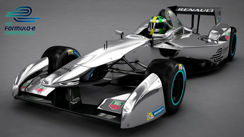
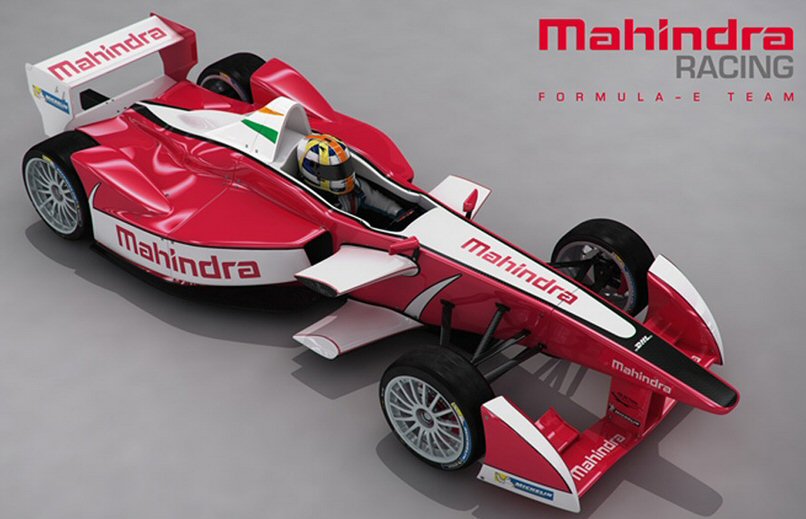
Formula E, all electric racing formula cars (Nov 2014)
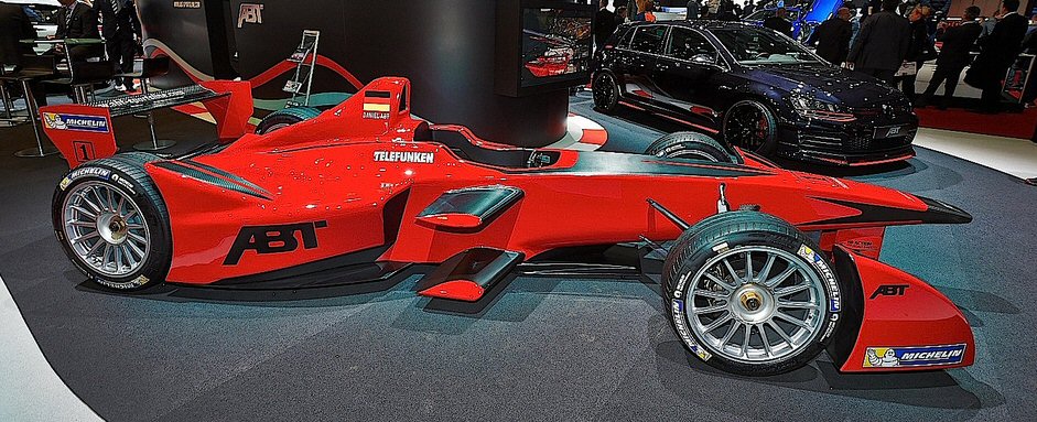
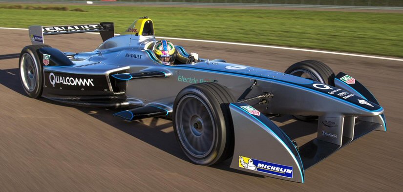
===================================================================================
Update Jan 2014
Now about
6-8 months since the 787 Dreamliner started flying again and the fleet
of 50 when grounded has expanded to 115 787s delivered (38,000 flights,
72 million miles), and the first (real) battery fire has happened.
On the whole Boeing must be feeling pretty good. Fleet is now >2 bigger fleet than when grounded, and this is the first cell to burn up. The protections seem to have worked. The fire didn't spread beyond one cell (I suspect they were lucky here), and the smoke it generated was vented outside alerting the ground crew that the battery had failed. One key fact is missing though, Is this one of the old cells or newly manufactured?Did Boeing Battery Work as Designed? (Design News title 1/17/14)
"The 787 Dreamliner's latest battery dustup occurred this week during pre-departure maintenance on a Boeing 787 parked at Tokyo's Narita International Airport. Japan Airlines mechanics noticed white smoke spewing from the bottom of the fuselage and found a possible failure of the main battery on cockpit instrumentation, according to a memo distributed by the airline (and sent to us via email by Boeing). "The safety pressure relief valve connecting to one battery cell out of eight was found to have opened, and it was found that liquid had dispersed in the main battery enclosure."
http://www.designnews.com/document.asp?doc_id=271116&cid=nl.dn14
Design News
contacted battery expert Prof Sadoway at MIT and he emailed back: "If you
had your car in for an oil change and the battery started smoking, would
this be OK? It's clear to me that the battery is unstable and that they
have taken steps to contain its failures." (yup)
---------------------------------------------------------------------------------------------------------------------------------------------------
FAA and Japan sign off (5/1/13)
Clearly Boeing
had earlier struck a deal with the FAA and Japan eq, because both quickly
signed off on the Boeing 'battery in box' fix. It takes a Boeing team about
5 days to modify each production plane, and commercial flights are scheduled
to resume June 2013. United is flying its 787s to a Boeing facility in
Texas to have the work done.
The FAA required a single test flight to verify the fix. What a joke, especially since the batteries are not used in flight. The Japanese are more concerned and (I think) I read each modified plane will be flight tested, and they are also requiring additional battery monitoring be added. A Boeing engineer summaries the fix this way:
"We provide three layers of protection in our solution set," Mr. Sinnett said. These include minimizing the probability of a single-cell problem, minimizing the probability of spread of any problem to other cells, and preventing an impact on the airplane.Boeing reveals details of its 'permanent' battery fix (3/15/13)The measures include wrapping the batteries in insulation and setting them in new stainless-steel containment boxes, as well as introducing vent lines that release vapors outside the airplane to reduce the possibility of fire.
Same blue sheet metal box!
I assumed
at a minimum the inside of the battery would be substantially changed,
cells further apart, probably the PC boards moving away from the cells.
Instead, look at the pictures, the blue thin sheet metal battery
box is still there! What they are going to do is put the existing
battery (with very minor changes inside) into a fireproof outside box with
venting! That's it, that's the fix. Amazingly, they are not even going
to change the cells. All the rumors about changes to prevent the fire from
jumping from cell to cell (apparently) comes down to just wrapping the
batteries in kevlar tape and putting thin disks of fiberglass between the
batteries. Boeing graphics and video show several other little tweaks inside
the battery box, for example locking nuts are now used on the battery studs
to attach the bus bars.
'Repurpose' the cells
The NYT story
on the details of the Boeing battery fix includes this classic: "The cells
from the existing batteries will be retested and repurposed." Really,
they are going to 'repurpose' the existing cells! What the hell does this
mean? Why not ask the ex-plane salesman, Ray Conner, who is now the Boeing
CEO for commercial aircraft, I bet he doesn't have a clue. It means, I
think, nothing. Amazingly they are going to reuse the existing cells rather
than replace them, so someone came up with this BS description. Why didn't
they have GS Yuasa make new cells? Is GS Yuasa production capacity is so
limited they can't make 800 new cells in three months? The announcement
includes the boiler plate that they are asking GS Yuasa to tighten quality
control, but they they say they are just going to repackage the existing
cells, two of which have burned up!
New fireproof outer box
Here's a close
up of the new (outside) battery box opened up. Look at the lower left corner
of the inside blue box: paint color, screw locations, grounding stud and
compare it to the lower left corner one of the burned Boston battery. It's
clearly the same thin sheet metal box! The NYT article text confirms this:
"Boeings solution, which company officials call comprehensive and permanent,
involves using the same battery cells and blue-box aluminum casing."
It looks like about all they did was put the existing battery in a strong
fireproof box. The added weight is 75 lbs per battery, so this must be
the weight of the fireproof box. Ironically all the weight saving advantages
of the lithium ion cells, which the CEO repeatedly said was the right technology
for the Dreamliner, are more than wiped out by the heavy outside box.
Clearly the battery is now much bigger in every dimension. It doesn't look to me that it would fit in the old bay (shown in the Boston NTSB photos), so it must mean it is going into some new location in the bay, maybe mounted on the floor. The penalty of increasing the battery size (if there is one) was not discussed in the news articles. Nor was there any mention about whether the monitoring circuits and PC boards (inside the battery box) have been changed.
Photos of new outside containment box with vent pipe (3/13)
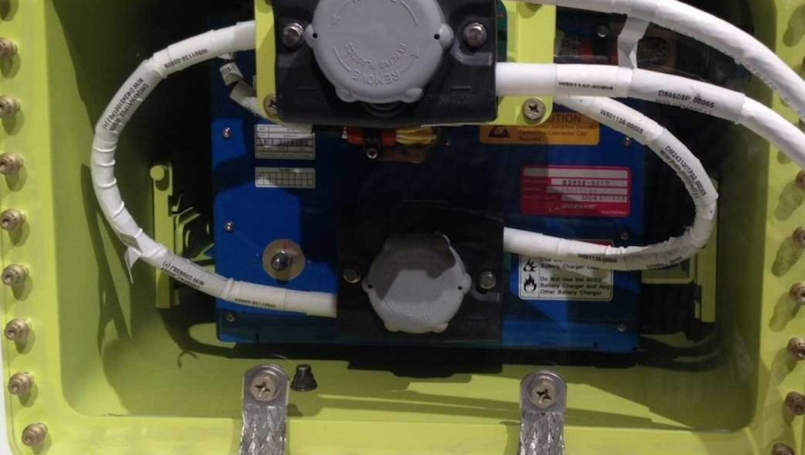 .
. 
left: closeup of the new, 75 lb, outside (yellow)
fireproof battery box showing the original blue battery box inside
right: burned blue battery box from Boston (NTSB photo)
Details of lower left corner (screw holes, ground
stud) show blue battery box is unchanged
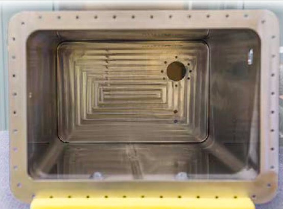 .
.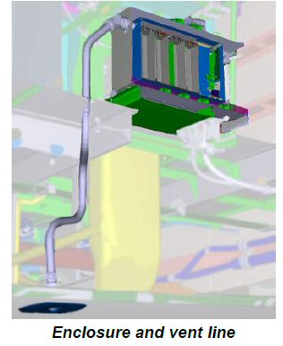
left: Boeing new 1/8 " stainless steel, sealed, explosion
proof, outside battery box
right: 1" dia titanium box vent pipe to a hole cut
in fuselage of plane (with valve)
(source -- http://www.boeing.com/787-media-resource/)
Tidbits
Some tidbits
of information are coming out about how sloppy the original battery development
was. Consider this beauty from the Aviation Week article:
-- The agency's (NTSB) investigation foundamong other thingsno record of the final production-standard charging system having been tested with the actual GS Yuasa-made battery. According to the NTSB report, Securiplane, the charging system developer, tested the unit with a simulated electric load instead of an actual battery. The company apparently took this precaution after having earlier suffered a fire at its facility during battery testing.It's unclear from this whether it means the charger was never tested with the actual battery, which would be mind blowing, or wheather this is referring to a production final test of the charger (most likely).
-- In a separate conference call, Ron Hinderberger, Boeings vice president of 787 engineering, told reporters each of the eight cells within each battery will be tested repeatedly under heavy loads of 18 kilowatts. Individual cells will be held to tighter parameters regarding changes in voltage and temperature. Boeing plans to perform the new tests on all new batteries, as well as those already in service. Any cell that doesnt fall within the new standards will not be used.This discharge power doesn't make sense for routine testing. The (absolute) maximum rated discharge current for each cell (from GS Yuasa data sheet) is 5C or 5 x 75A = 375A (the largest current in the cell curves is 250A). For the whole battery 375A x 28V = 10.5 Kw. Is Boeing going to stress every cell to 18 kw/10.5kw = 171% of its maxiumum discharge spec! (Very risky, overspec discharges could weaken cells). Another article I found says the 18 kw testing is to be on sample batteries. This is more reasonable. While I presume GS Yuasa must have approved it, I don't know if this is a mechanical/airspace engineer's idea of tough test, like loading a wing, or perhaps it's intended to identify some weakness in GS Yuasa manufacturing process.Another article puts the cell testing this way: As part of the testing, Boeing will cycle sample batteries through three episodes of a high 18 kilowatt load, for 30 to 45 seconds each.
Boeing has tracked the manufacturing records of all the cells in all 115 batteries now in service, and Hinderberger said that data identifies which cells wouldnt pass the new tests. Those cells will be rejected and the batteries will then be refurbished, he said. They will then undergo the same tests as newly manufactured batteries before being reinstalled on jets.
-- Neither battery is used in normal flight.The front battery is used to power up the cockpit in a dark plane. The rear battery starts the APU and runs its controller. So it does look like in 'normal' flight, i.e. engines running, the batteries are not used. Of course, there remains the bird strike problem, like happened at LaGuardia a few years ago, where both engines shut down in flight. If this happens the rear battery is needed to start the APU, which is needed to attempt to restart the engines.
-- The venting of gases from the sealed outer box to the outside is new. It is a 1" tube (looks like it's a few feet long) from the battery box and for both batteries a new hole is to be added to the fuselage. The stainless box will be sealed. If there is a battery overheating event, a valve will open in 1.5 seconds to vent air outside the aircraft, through two new exterior openings away from any air intakes.I am surprised that a mechanical rework like this this is not a big deal with the existing 50 aircraft, but the articles give no hint that it is. Baffled.
-- (Boeing chief engineer) said that the fire in Boston consisted of small flames outside the blue battery box, but that there was not a fire inside the blue box.Boeing is not inspiring confidence by in their presentation making (absurd) claims that there was no fire in the battery box and that cells did not set off adjacent cells. One only has to look at the charred, blackened interior of the Boston battery box (as well as the bay in which it was located) to see how laughable this claim by Boeing is.
-- New titanium fixtures are being installed in the electronics equipment bays to ensure the housing is properly supported.This sounds like a new spot has been found for the battery in the bay. Probably necessary since I seriously doubt it would fit in the old location. Also they need a location in the bay that is near the outside to minimize the lenght of 1" venting pipe they need to install.
-- Boeing site below details that battery testing at GS Yuasa has been upgraded, with additional screening and sample tests.Reducing the usable charge range (how much is not given) of course effectively makes this double weight lithium ion battery electrically smaller, at least in terms of energy storage (power rating is presumably unchanged).Tolerances at the battery level have also been tightened: lower maximum and higher minimum charge, in other words more derating. The battery controller charge current has been adjusted in ways not fully explained, but (reading between the lines) the peak charge current has probably been reduced (less heating) and its rise time increased ("softened" waveform says Boing), though I doubt the latter will do much.
-- The team demonstrated that fire cannot occur within the new enclosure. Its design eliminates oxygen, making the containment unit self-inerting. Even when we introduced a flammable gas in the presence of an ignition source, the absence of oxygen meant there was no fire.Boeing has a day by day timeline of the engineering work done over the last 10 weeks. It makes no mention that any change of battery or supplier was ever considered. In fact it shows within three days after the Jan 16 grounding of the plane work was already focused on a containment box for the battery.-- A comparison chart comparing the 787 lithium ion battery to the NiCad used on previous Boeing planes gives the discharge current: 150 A (or 2C). This is well within the battery discharge spec of 5C maximum and 250A shown on the curves.
-- Boeing talks about their flight testing of the proposed changes. Since the batteries are not used in (normal) flight, presumably this amounts to monitoring the battery voltage and current while it is doing nothing (neither discharging or charging). To get a good look at the no load voltage, they installed special equipment sampling every 2 usec.
-- Jan 19, Development team considers a variety of potential designs to improve the containment of the 787 batteries and selects one for additional development
-- The only possible cause for thermal runaway at an airplane level is overcharging (this apparently applies to the old battery as next to it is a picture of the burned up Boston battery)The slides of the Boeing chief engineer detailing the fix (3/15/13) makes the absolute statement above, "only possible cause". (really!) There is a fudge 'airplane level' whatever that means. What about an internal short in one cell? Boeing seems to be saying that even in the old battery the heat from shorting of one cell couldn't trigger failure in the other cells. But there is a huge problem with this claim! The plane's data recorder shows no overcharge, the voltage drop to 28V appears to be a single cell shorting, and the whole inside of the battery box is a burned, blackened mess. The very next chart shows the most likely scenario was a single cell "heating" followed by "cell to cell propagation".
Description of the fix from Boeing, overview and details
supplemental info
http://boeing.mediaroom.com/index.php?s=43&item=2622
http://www.boeing.com/787-media-resource/
http://www.nytimes.com/2013/03/16/business/boeing-details-its-fixes-for-787.html?_r=0
----------------------------------------------------------------------------------------------------
(2/20/13 update)
Boeing has
released a 5 min video (below) of the 787 project engineer discussing
the batteries on the 787. Re: the battery problems grounding the fleet,
this is a real PR puff piece. No mention of fire (or even overheating),
it only acknowledges the batteries had a 'fault'. He says "hundreds
of people are working 24/7", but gives no info on what they are doing,
have found, or are thinking. His talk is in front of an audience, yet he
takes no questions. It does, however, provide some more info about what
the batteries do.
APU (rear) battery
The APU (rear) battery
besides starting the APU it powers the APU controller and also some of
the plane's navigation lights. If it routinely powers the planes running
lights, it is used during flight. This ties in with a little news
story today that the Japanese investigator says the tails light of the
problem plane there were seen to flash on landing. In the Japanese plane
it was the front (main) battery that burned up, so the implication
of the flash is that it burned up when the plane was landing and that the
two batteries seem to have been wired together somehow (incorrectly says
the headlines) and that the front battery shorting overloaded the rear
battery until some current limiter could kick in.
Main (front) battery
The main battery
is the first thing switched on when the airplane is cold and dark. It powers
up the cockpit and provides support for refueling on ground. It also can
provide the power to run the brakes, which allows the plane to be towed
with its APU and engines off.
One slide compares the specs of the lithium ion battery in the 787 Dreamliner with the nickel cadmium battery used in the older 777 plane. The striking difference is in the current (and power). Although the NiCad battery is heavier, its current (and power) are shown about an order of magnitude lower than the lithium ion 787 battery. There's something funny here. Need the cell spec for the 777 to figure this out. Missing from the chart are the batteries' energy storage. It might be that on the 777 the battery is designed for low power that can be sustained for hours of flight. I know the 787 cells are rated 75 Ahr, so that means they can deliver 150A for 30 min max.
Boeing 787 project engineer talks about the 787 batteries
http://787updates.newairplane.com/787-Electrical-Systems/Batteries-and-Advanced-Airplanes#gallery/2168040449001
Latest installment in the Boeing Dreamliner battery saga (2/15/13)
Boeing CEO and CFO in a telephone call with financial analysts in Jan went out on a limb reaffirming the switch of the battery technology in the 787 to lithium ion was the right decision. The investigation has been sawing on that limb as no explanation for the shorting of the cells has yet been identified in six weeks. Also the proposed (whispered) Boeing 'fix' of repackaging the existing cells in a fireproof box is half-assed, which I am sure the engineering staff understands even if Boeing management doesn't. All repackaging does is contain a fire, it doesn't prevent a fire, and if there is a cell short, the whole battery goes down. Some fix!
Another shoe drops
During the Boeing
call one of the justifications Boeing gave for sticking with lithium ion
was that airbus was planning to use lithium ion too in its new A350 wide
body coming in 2014. Whoops, airbus is now sawing too.
A NYT article today (2/15/13) says airbus has decided to switch the battery in its production A350 planes from lithium ion, which is used in their prototype A350 plane, to their usual battery technology of nickel-cadmium (NiCad). NiCad batteries (used in planes) have lower energy storage, but higher peak power than equivalent NiMH batteries (used in hybrid cars). I don't know how a switch to NiCad would affect the battery size, because I don't know if the Boeing applications are sized on energy storage or power. The NYT article quotes someone as saying the extra weight for airbus to switch from lithium ion to NiCad can either be absorbed by plane's design margins, or at worst there will be a reduction in the plane's capacity of one passenger, which is what I estimated earlier for a switch to NiMH. The cell voltage of NiCad (and NiMH) is only 1.2 V vs 3.7 V for lithium ion, so that means internally the batteries are completely different. A 30V battery like Boeing is using can be built from only 8 lithium ion cells, but a switch to NiCad means a minimum of 25 cells.
If I was a betting man, I would now be giving odds that Boeing is going to have to remove the lithium ion battery from all its 787's. Probably the trickiest problem if it drops back to its old battery technology, is to where to put a second (or double) battery box. From the pictures of the electrical bay in the center of the plane it fit into a small slot. The new battery won't fit there, at least not all of it. The front battery is mounted under the cockpit. I haven't seen a picture of this bay, so don't know how much room it has.
For Boeing
to save face I wouldn't be surprised if it is whispering to the regulators
(National Transportation Safety Board), 'force us to remove the lithium
ion battery', the technology is not yet safe. Boeing management can then
blame the huge time and cost penalty to get the planes back in the air
not on their mistake, but the 'government made us do it'. The Republicans
will then pile on, saying Obama is to blame, too much job killing regulation!
-----------------------------
What do the batteries do? (2/11/13)
Short answer
appears to be they provide backup power. They are not used in normal flight
says an Economist article. (knowledgable poster says) Batteries in
the 787 are not much more powerful than the 777 or other similar planes
for they serve pretty much the same purpose: start the APU (a small turbine
generator) and power critical instruments in some emergency scenarios.
Here's my 2/11/13 email on what the batteries do, written after some research:
http://www.boeing.com/commercial/aeromagazine/articles/qtr_4_07/article_02_3.htmlFrom Boeing document below: Dreamliner's electrical power in flight
comes from two big (250 kw) generators in the engines or (usually on
ground) from big generators run by a small turbine engine in tail called
APU (Aux Power Unit). Battery power in contrast is tiny (2kw or 1% of
generator power).Loss of both engines in flight (say, double bird strike) means loss
of the only generators. It is then vital to immediately start the APU in
the tail with its large generators. If I read the Boeing document
correctly, in flight with the two engines down the ONLY way to start the
APU is with the (rear) battery, that's its job. And only with the large
APU generators running do the pilots have the power to try and restart
('relight') the engines in flight.A (rear) battery down with a single shorted cell means the entire
electrical backup system is dead! Lose two engines and the plane has no
power (except for a low power ram air turbine), guaranteed crash. I am
appalled that no one at the NTSB or Boeing or the press has to my
knowledge ever mentioned this risk in public if the 'fix' is to just
repackage the existing GS Yuasa battery cells, which are going bad for
unknown reasons.
Don
Key text:
-- "The power
source for APU starting may be the airplane battery, a ground power source,
or an engine-driven generator. The power source for engine starting may
be the APU generators, engine-driven generators on the opposite side engine,
or two forward 115 VAC ground power sources."
The press focuses
entirely on the fire problem, but in fact Boeing
has two, or depending on how your count, three problems
with their
battery. It's pretty well accepted now by the investigators
and Boeing
that the problem is 'in' the battery, that one of the
cells is shorting
and igniting. The fire then spreads from cell to cell
burning up the whole
inside of the battery box. The three problems are:
1) Cells for unknown reasons
are failing (shorting internally), and
because they are lithium when they short they get real
hot and ignite.
2) Cells are large and packed
close together with no fire or blast
protection between, so when one cell catches fire it
ignites adjacent
cells and eventually all the cells. Burns up the PC protection
boards
which are inside and not protected either.
3) The outside metal battery
box is supposed to contain a fire. It
doesn't, it allows flaming liquid to leak out. The first
technician on the
scene at Boston saw flames coming from the box, and the
bay where the box
was mounting shows the fire escaped.
Boeing is making
noises about 'strengthening' the battery, which
translated means repackaging the cells. Put the cells
they have in a
bigger box, pack fire or blast absorbing material around
them, and make
the outside box fire proof. This would be the quickest
thing to do because
they could continue to use the cells and PC boards they
have, but it's
basically a half ass 'fix'.
It might 'fix'
the fire problem (by keeping the fire small and
contained), but there's another problem. Cells are dying
and one dead cell
in a battery means a totally dead battery. What's the
safety risk if a
battery is lost during flight? Boeing never says, and
no one in the press
ever asks. I read one of the batteries is there to start
a small turbine
engine that runs a generator for emergency power. This
sounds pretty
important to me. Just repackaging the existing cells
means living with
this risk.
A new
cell type or cell size means a whole new battery design which
will take time. The right lithium fix (I think) is do
what Tesla does, go
to a small reliable cell, work with Tesla.
However, the
regulatory people are on the edge of telling Boeing
take the damn lithium ion battery out of there, if for
no other reason
than this covers their asses. And because they told Cessna
recently to take
their lithium ion battery (totally different design)
out of their new
business jet after it caught fire and totally destroyed
a plane. A
non-lithium fix would likely mean leaning on knowledge
and experience of
the hybrid car people and use the type of non-flammable
battery (NiMH)
they have used for ten years, which is what I suggested
on day one.
I'm wondering if
repeated pressure changes of commercial flight might
be affecting the battery cells and causing their failure.
They look like
they might be sealed, so they would be continually expanding
and
contracting. Boeing in today's NYT story listed all the
tests they did on
the battery, but I didn't see pressure cycling. It's
just the kind of thing EE
engineers, who are probably doing the battery testing,
might miss because
it's not electrical, but still for an airplane company
to miss something
like this would be a big screw up.
Don
---------------------------
(2/8/13)
Over the last two
days there have been two stories in NYT about the Boeing battery. On Wed
NTSB says it will be several more weeks before they can determined
what happened with the Boeing batteries, so it looks like the fleet is
going to be grounded for another month.
On Thur the NTSB chairwoman (Debra Hersman) said directly what all the evidence was pointing toward, that the problem is (very likely) in the battery, that one of its cells is shorting (and igniting), and then the fire spreads to the rest of the cells. Boeing accepts that cell failure (shorting) is probably the cause of the fires.
Two (or three) problems!
What the news
stories fail to point out is that Boeing has (at least) two fundamental
problems with the battery. The press stories are all about the fire risk,
but that's not the whole story. If a cell shorts in a battery box, you
have lost the battery. Are either of the two batteries on the plane needed
for safe flight? How critical are they? I know the job of the battery in
the rear is to start an emergency turbine for backup power. Sound pretty
important to me, but it is a backup task, so a calculation might show the
risk of a failed battery in flight might be acceptable for a few hours
to get the plane on the ground. Still I'm skeptical this argument would
'fly'.
The other, and clearly more serious problem, is how the cells and battery protection PC boards are packaged. There are all crammed together into a metal box with no fire or blast isolation between components. It's now all too clear that heat and explosion of one cell ignites its neighbors and burns up the PC boards too. Even worse, and really a 3rd problem, is that the metal box is failing to contain the fire, it's allowing flaming electrolyte to leak out of the box. Just look at the fire damage to the bay in which the Boston battery was mounted. The first technician on the scene reported seeing flames coming from the box. Some box!
What to do?
The press
never mentions that a battery redesign at this point requires key decision
to be quickly made: Keep the existing cell or change the cell. It would,
I am quite sure, be far easier and quicker to 'repackage' the existing
cells from GS Yuasa and probably easier to requalify the battery. Put them
in a bigger, stronger, fire sealed box with fire and blast protection packed
around are each cell and probably the PC boards outside.
The problem is this only addresses the fire problem. If the cells have quality (or pressure problems), then they are going to have batteries being lost in flight with whatever risk this entails. A variant of this approach would be to add or change vendors for the cell.
A more fundamental redesign, while retaining the advantages of lithium ion, would be to go the Tesla route. Change both the cell and packaging, probably working with Tesla to come up with a new battery.
A (possible interim) high quality fix would be to replace the lithium ion battery with a NiMH equivalent. It would be about twice the size and would require new protection PC boards. Build on the long experience and knowledge of hybrid car builders.
New data -- sudden drop in voltage
New data from
the Boston plane was released today (2/8/13) that strongly supports the
theory a short in a cell triggers the failure.
NTSB chairwoman Hersman said that "flight data from the Boston plane showed that the battery's voltage unexpectedly dropped from a full charge of 32 volts to 28 volts, which suggested that problems began in one of the four-volt cells." (actually they are 3.7V cells nom, and the nom battery voltage is 29.6V, though 32V is possible at the end of a charge cycle)Strengthen
Boeing now says they recognize that it will take a "combination of changes" (translation: redesign) to restore confidence in the battery system and are working on a range of possible technical overhauls.Spare battery?These include making the battery cells more resistant to shocks to keep excess heat from spreading from one cell to another, causing the kind of thermal runaway that occurred in the two recent events. Boeing officials have said they are also working on building more solid containment cases and better venting mechanisms in the event of overheating." (translation: repackaging the existing cells) (NYT 2/7/13)
Boeing said they also have a team working on "more conventional batteries" in case the FAA tells them (quite likely I would judge) get the lithium ion batteries out of there. (NYT 2/8/13)
Boeing for the first time detailed all the thousands of hours of tests they ran on the batteries apparently finding nothing (or covering up!), because they predicted to FAA during the certification millions of flight hours before a battery failure. The tests included the 'nail' test and other destructive cell tests. On the surface it sounds thorough, maybe it was and maybe it wasn't, you can't tell from what is in the NYT article.
For example, the 'nail test': Was this run on an isolated cell or on a cell mounted in the battery box with seven other cells? If I was a betting man, I would bet it was run on single cells for two reasons: it's far easier to run on an isolated single cell and this test would be a confirming test to a test probably either in the battery spec or done by GS Yuasa. But if done this way it would not have revealed a huge design flaw, that a single burning cell can ignite all the other cells in the box.
Are repeated pressure changes damaging the cells?
It occurs
to me that a possible cause of the cell shorting might be internal damage
from repeated pressure changes. I have never seen this even mentioned in
the press. This is the kind of thing that could easily be missed by the
electrical engineers running battery tests both at Boeing and GS Yuasa.
Boeing says they flight tested the battery, but the thousands of hours
given were for both lab and flight together. It's known the two fires occurred
within a week of each other. The critical piece of data, never released,
is did the two batteries that burned have somewhere around the same number
of landings and takeoffs?
----------------------------
Energy in a single cell
Each of the
eight cells in the Boeing battery cells is unusally large: 7" x 6" x 2",
weight 6 lbs, able to deliver 75A at 3.7V for an hour. The speced max current
is 375A and calculated short circuit current is almost 5,000A. These large
cells store an amazing amount of energy, in round numbers a cell can deliver
to an external load 1,000 watts for 15 min (at 300A). If a cell develops
an internal short, say a pinhole in its 1 mil thick separator layer, the
current is going to rise to 3,000A to 5,000A and all the energy stored
inside is going to be dissipated inside the cell, 10,000 watts for up to
90 seconds. Yikes!
It seems intuitively that 10k for over a minute is going to burn the cell to a crisp, but let's check this. A simple, conservative assumption is that the whole cell is made of carbon. The electrodes are largely carbon and the electrolyte is organic (hydrocarbon), which means by weight it is mostly carbon too. The thermal capacity of carbon is 0.71 J/g K.
Temp rise = 0.71 x joules/grams
= 0.71 x (1,000 watts x 900 sec)/(6 lb x (1 kg/2.2 lb) x (1,000 gram/1
kg))
= 0.71 x 900,000 joules/2,727 grams
= 234 C
Not quite as high as I would have guessed, but the cell is certainly going to fail long before it's temperature rises by 234C. This 234C (potential) temp rise simply reflects the energy density of the Boeing cell, which is 100 kwh/kg. Tesla's cell packs twice the energy into the same mass (200 kwh/kg), so its (potential) temp rise is twice as high (468C = 2 x 234C).
I don't know
enough about lithium batteries to say if this energy would produce a fire.
To get a handle on that I looked on YouTube and sure enough a bunch of
videos shows lithium ion batteries being destroyed. Most were doing stupid
things like overcharging, in water, in a microwave, being squeezed, but
still these test were scary because they showed lithion cells can really
explode and burn. One video was more relevant to what may have happened
at Boeing: a nail was driven into a charged cell producing an internal
short circuit. A cell short circuited internally will begin to rapidly
dump its stored energy into itself . A nail driven into two small cells
produced a ton of smoke and a flaming wreckage.
-----------------------------------------------------
Update 2/6/13
An email to
friends summarizing my latest thinking on the Boeing battery problem from
a Tesla perspective. (I glossed over and/or simplified some unimportant
engineering details in this email):
Boeing should learn from Tesla
Following up on public statements by Elon Musk (cofounder of Tesla) about the Boeing battery problem, I have recently made some interesting discoveries by looking into how Tesla makes their batteries.
The Boeing battery is a 30V, 75A cobalt lithium ion battery. Turns out that the 366V battery in the Tesla electric cars is made up of sub-batteries each of which is 33V, 150A. In the attached photo the Tesla 33V sub-battery (in roadster) is the green thing (2.25 sq ft x 4.5" thick). It's smaller physically than the Boeing battery, but electrically it has the power of two Boeing batteries AND uses the same (or very similar) cell chemistry. There are 11 of these 33V sub-batteries in every Tesla electric car stacked up in series.
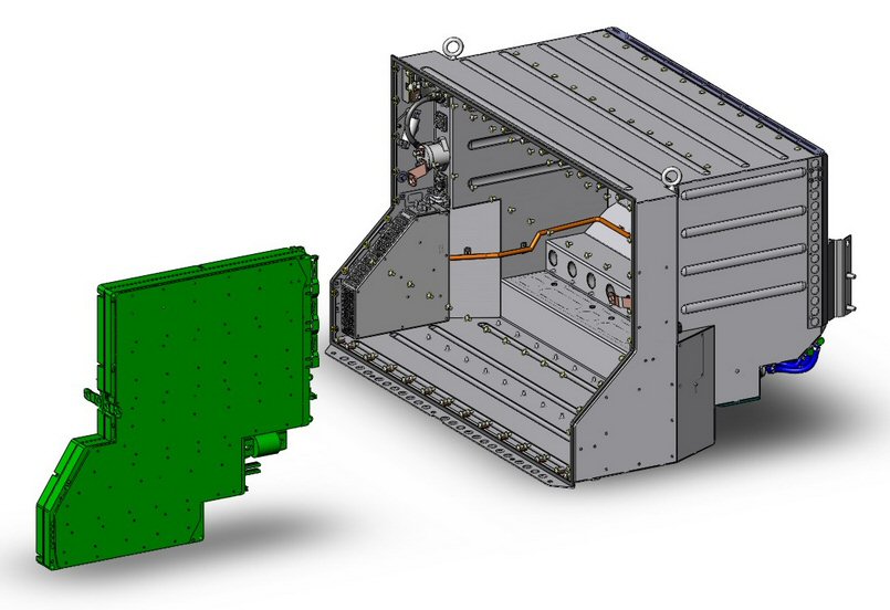
Tesla roadster battery rack showing one of eleven
33V, 150A sub-batteries
Never a fire!
Tesla has built to date
about five thousand of its two cars (current build rate is 800/month),
which means it has made (11 x 5,000) = 55,000 of its 33V, 150A lithium
ion sub-batteries. Musk says Tesla has NEVER had a fire in any of their
production batteries. On the other hand Boeing has fielded about 100 (2
per plane) of its smaller lithium ion 30V batteries and had THREE fires
(2 at customers and 1 in development). Tesla: 0 fires in 55,000, Boeing:
3 fires in 100. The numbers pretty clearly say Tesla knows how to build
a safe high current 30V to 33V lithium ion battery and Boeing doesn't.
It's cell size
So what's the important difference?
It's the cell size. A single Tesla cell is x60 lighter than a Boeing
cell (45 grams vs 6 lb or 2.7 kg)! The Boeing 30V battery is composed of
8 huge cells (8 x 3.7V = 29.6V). The Tesla 33V sub-battery is composed
of 621 small cylindrical cells (9 x 3.7V = 33.3V) arranged (9 x 69 parallel
= 621). It turns out cell size is very important if a battery develops
an internal short.
How a cell burns
Lithium ion battery cells internally
are a stack up of a thin triple sandwich (+, insulator, -). The insulator
material is only 0.001 inches (1 mil) thick. If it develops a pinhole,
the current will surge though the tiny short and local burning will start.
Because the reaction releases oxygen, the burning will quickly spread through
the whole cell. There is nothing than can be done externally to stop this
once it starts.
YouTube
People on
Youtube like to blow things up, and lithium ion batteries blow up nicely.
There you can see that just a couple of small lithium cells can really
explode, pouring out fire and smoke. Boeing's huge 6 lb cell burning internally
would be like a little bomb. This is why I think Musk said the Boeing battery
is "inherently unsafe". It says to me Boeing's battery has a DESIGN flaw.
Four Tesla advantages
1) Of course if a Tesla cell develops an internal
short, its insides will burn the same way, but with 60 times less material
it will be a much smaller 'pop'. A critical point is a smaller, lower energy
explosion is much less likely to trigger a fire in neighboring cells. Musk
made this point in his comments. This advantage is aided by geometry of
the Tesla cell and how it's packed in the sub-battery.
2) Tesla packs the cylinderical cells touching (or almost touching) in a single layer, which since they are round, means they only touch at four small points. If an individual cells explodes in fire, the much smaller explosion, combined with air separation, and at the four touch point two metal cans, the data seems to indicate is enough to keep the fire from spreading to adjacent cells.
Based on my experience blowing things up (inadvertently) in the lab, my guess is that a burning Tesla cell would tend to burn open (or blow 'clear' as we say in the engineering biz), because of the huge energy available in the parallel cells. (Only Tesla knows for sure how often a burning cell would clear.) Since Tesla wires 69 (yes 69!) of its 18650 cells in parallel, the loss of one (if blown open) would mean nothing. Not only would there probably be no serious fire, the battery might very well continue to work. (There is an issue here, however, for Boeing that Tesla does not have, because for Tesla if it does not clear it's a dead car, but for Boeing they have lost a battery in flight.)
In addition to Tesla's advantage of cell size and geometry, there are two other safety advantages of its small cells, and it is difficult to tease all these factors apart.
3) The 18650 cell is made in the "billions" (says Tesla). They are used in laptops and a million other devices. Because they are made in huge volumes on highly automated machinery, they are very reliable (says Tesla). In contrast the large Boeing cells are made in small quantities (almost by hand you might say) just for airplanes. Boeing has bought what, 8 x (100 or 200) of them. Any other customers?
4) The 18650 lithium ion cell is a sophisticated highly engineered structure. Each 18650 lithium cell has built into its cap two current limiting devices: fast acting electronic fuse (PTC) and mechanical fuse (bimetal probably). These don't do anything to protect from an internal short, but it allows Tesla to parallel 69 cells, and these fuses will (likely) prevent most of the electrical energy of the other 68 cells from dumping into the cell with the short.
When most people (including me) first hear that Tesla is using 6,831 small little cells in their electric cars, it sound like a cludge, but maybe it's not so dumb, or even smart. At this point it seems that using lots of small cells is a good way to reduce the fire risk of flammable lithium cells. No fires (assuming Musk is not lying!) in 55,000 (and counting) 33V sub-batteries is impressive.
Musk said he has been in contact with
the Boeing's chief engineer and is offering them Tesla's help.
Don
Update 2/1/13
The sage continues.
The recent comments by Elon Musk of Testla and SpaceX are getting quite a bit of play. Musk said he has been talking to the Boeing chief engineer, and told Reuters that that SpaceX battery packs could help the Dreamliner. Musk included this helpful data:
We have never had a fire in any production battery pack at either Tesla or SpaceX, says Elon Musk (Tesla Motors has sold 2,500 Roadsters and 3,000 Model S)
Comparison to Tesla battery
It interesting to
compare the Boeing battery to the Tesla battery. The only detail battery
package data I can find is for the older Tesla roadster. Tesla in Roadster
and Models S (and probably SpaceX rocket) use size 18650 (18 mm dia, 65
mm long) cylinderical lithium ion cells, a billion of which are manufactured
each year. Tesla's sole supplier in recent years is Panasonic. Panasonic
data sheets indicate they use cobalt oxide, but I read the Model S Panasonic
cathode is nickel-cobalt-aluminum. The Roaster cell was 2.2 Ah (44 grams)
and (planned) Model S cell is 3.1 Ahr (44.5 grams). (A 4 Ahr is reported
to be in development in this same size.) The Panasonic 18650 cell has a
PTC built into the cap (no ESR spec).
The Roadster battery 56 Kwh (215 Kw pk) pack was built up from eleven 33.3V battery 'sheets' that plug into a rack. Each 33.3V 'sheet' has 621 cells arranged as 69 cells wired in parallel to form a 'brick' x 9 bricks in series (9 x 3.7V = 33.3V and 69 x 9 = 621 cells). The total roadster battery pack used 621 x 11 = 6,831 cells. 6,831 x 2.2 Ahr x 3.7V = 56 khw (rating of the roadster battery pack). The weight of all 6,831 cells is 661 lb = (6,831 x 44 gm x 2.2 lb/kg) with the total battery weight (including liquid cooling and metal frame 990 lbs. (All this info is from Tesla web site)
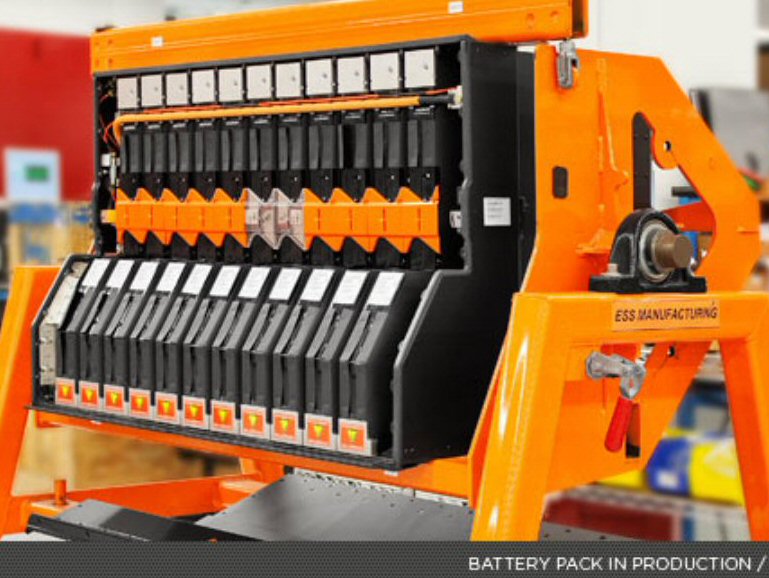 .
. 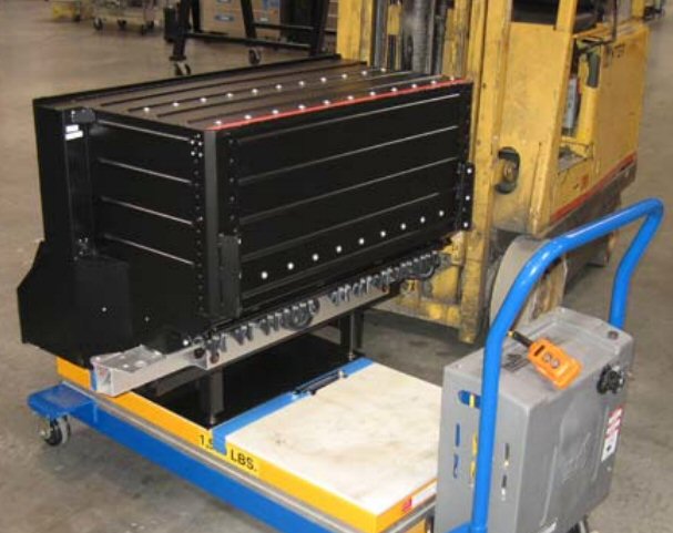
Tesla roadster 56 kwh battery pack
(left) clearly show the number of 33.3V thin 'sheet'
batteries is 11
(right) allows the dimensions of the pack to be estimated
(using push cart as reference)
(621 cells/sheet x 11 sheets) = 6,831 2.2 Ah
(65 mm x 18 mm dia) cells
green shows 1 of 11 series 33.3V 'sheet' batteries
(11 x 33.3 = 366V)
1 C current rating = 69 x 2.2A= 152A
each sheet is 69 parallel cells x 9 series = 621 cells
total
energy rating of 33.3 V 'sheet' battery is 5.05 kwh
= (33.3V x 69 x 2.2 Ahr)
Tesla 'sheet' batteryComparing the Tesla (roadster) 'sheet' battery to the Boeing battery
Can't find the dimensions of the roaster battery pack (mounts directly behind the two seats crossways), but from the picture on the push cart (above) we can make a pretty good guess as to its length. The battery pack overhangs the pushcart a little, so I would guess it 4 to 4.5 ft long. This makes the width of each 'sheet' battery module (4.25 ft x 12 in x 0.95/11 = 4.40" nom). Each 65 mm cell is 2.56" tall, so almost for sure there is a single layer of cells inside. The minimum area of the sheet would be if the (round) 18 mm dia cells where touching, so sqrt{621 x 18^2} = 448 mm (17.6 inches) on a side. This looks reasonable, since looking at the pack on the cart it could easily be (rectangular equivalent) 1.5 ft (high) by 1.5 (deep). Hence we find the 621 cells of each (green) 33.3V, 152A (1C) 'sheet' battery must be in a single layer with their sides touching (or nearly touching).
** 18650 cells typically have a PTC built into the cap. Test for NASA show cell short circuit current 2.8V/34A = 82 mohm. This is the sum of the ESR + PTC + 10 mohm ? (ext short). Tests by some poster of mongral Chinese protected (PTC + PC board with Si switch for OV) 18650 cells shows them all about 100 mohm (.2V sag 1A to 3A).
But 22 mohm in graph in same paper. Tesla roadster battery pack peak power implies (215 Kw/6831 = 31.5 watt/cell) gives about 10.5A/cell peak (1 C = 2.2A) since (3.0V (guess) x10.5A = 31.5 w). So a sag at peak to 3.0V implies a total ESR (including PTC) of 67 mohm, while a sag of one volt to 2.7V allows ESR to rise to 86 mohm. A detail table at this site of 18650 lithium ion cells shows Panasonic has a typical ESR of 100-110 mohm (including protected cells).
http://lygte-info.dk/review/batteries2012/Common18650Summary%20UK.html
Paper on Lithium ion battery packs using thermal abuse
models
Discusses
the PTC built into size 18650 cells for a NASA 16P-5S (16 parallel, 5 series)
battery.
http://www.nrel.gov/vehiclesandfuels/energystorage/pdfs/45388.pdf
-----------------------------------------
Model S chemistry
Model S chemistry
I couldn't pin down. In 2011 the buzz was the model S would use the new
panosonic nickel ( LiNiO2 ) 3.6V cell NCR18650A 2.9 Ah. However, posters
in 2012 think it's a new tweaked cobalt chemistry from Panasonic with aluminum
added.
Here is the NCR18650A on Ebay (plus a 'protected' version with a built in Seico PC board and FET on/off switch).
http://www.ebay.com/itm/PROTECTED-3100mAh-18650-Li-ion-PANASONIC-NCR18650A-TOP-Button-Battery-ORBTRONIC-/330721085837?ssPageName=STORE:HTMLBUILDER:SIMPLEITEM&refid=store
-----------------------------------------
Update 1/31/13
Airlines have
had to replace the Boeing lithium ion battery about a dozen times in the
few months it has been flying, often with the complaint that it would not
charge, generally just returning the batteries to their maintance dept.
These 'bad' batteries might contain a wealth of information. While it could
be a lot of things, it is possible that the reason some of the batteries
wouldn't charge (or output current normally) is because one of their 8
cells suffered an internal short. It might very well be that if a
cell shorts (internally) and burns up, it often (or usually) doesn't didn't
trigger a thermal runaway in its neighbors. In other words it's possible
the problem of bad cells has been present but not recognized.
The counter argument would be wouldn't the airline maintaince dept should have returned these 'bad' batteries to Boeing (or supplier) to have them looked at, but there was no indication in the early articles that they had.
Battery people speak out
-- "The lithium ion batteries installed on the Boeing 787 are inherently unsafe, says Elon Musk, founder of SpaceX and owner of electric car maker Tesla.
--Battery expert
George Blomgren, who worked for Eveready for 40 years told CBS news that
from what he knows about the incidents on board the Boeing 787s he would
'not fly in a Dreamliner tomorrow.' (nor would I)
----------------------------
Today's email trail...
Don
Well it keeps
getting more interesting doesnt it?
-- Elon Musk Says 787 Batteries Are Inherently Unsafe. Flight International (1/30, Rosenberg) reported, "The lithium ion batteries installed on the Boeing 787 are inherently unsafe, says Elon Musk, founder of SpaceX and owner of electric car maker Tesla." Musk said, "Large cells without enough space between them to isolate against the cell-to-cell thermal domino effect means it is simply a matter of time before there are more incidents of this nature." The article noted that "while Boeing elected to use a battery with a grouping of eight large cells, Tesla's batteries contain thousands of smaller cells that are independently separated to prevent fire in a single cell from harming the surrounding ones."
-- The Atlantic
(1/30, Fallows) reported, "The simplest version of Musk's complaint is
that Boeing has concentrated the battery power in too small a number of
large cells located too close to one another - rather than dispersing the
power among smaller, more widely separated cells."
--------------------------
Yea, sure does. I hadn't seen Musk's comments. That should
carry some weight.
I'm not sure I buy his argument though. The Tesla model S has the cylinderical batteries touching or virtually touching each other. But maybe because the cells are so small there is not enough energy to trigger the next? The GS Yuasa Boeing cell data spec sheet is online so I did a calculation of the ESR power, and it was fine (2-3 W/cell). The open question is what sets a cell off? Does it only take pinhole in one of the 25 um separators?
I'm surprised Musk doesn't mention the chemistry (cobalt) and no one (but me) has commented on the the dumb idea of mounting the battery control boards inside the battery
Nothing of what Boeing is doing in the lab has come out. Are they finding the battery catches fire easily or is a bitch to ignite? I'm not surprised that Boeing top management says nothing until they come to a decision. But they are really stuck and are going to have to do something pretty soon if they want to keep selling planes. Also I would assume this problem is probably threatening the financial stability of Japan's ANA airlines, which has about 17 planes it can't fly.
I would put
the odds that they change the battery (in some way) at 80-90%. In three
weeks they have not been able to point to a quality problem, so I don't
see how they can PROVE that the existing battery is safe (especially when
it probably isn't!). And math idiot Ray la Hood, Sec of Transportation,
has set the bar pretty high at 1,000% confidence.
Don
-------------------
Don,
I agree that
Musks comments should carry some weight but all I heard him say was how
great his solution is. It seemed like more of a marketing promo for the
Tesla design vs. addressing the Boeing problem. As you say I cant imagine
why he didnt pick up on the battery chemistry?
-----------------------------------------------------
Update2 1/29/13
New information
released: many pictures and details about the Boeing Jan 7 battery fire
at Logan airport (Boston) were released today by NTSB. It shows:
1) Boston battery was totally burned up inside just like the battery in
Japan.
2) This was a serious fire. Picture taken outside plane when firemen arrive
shows a lot of smoke coming out. First technician on scene reported "flames"
coming out of the battery box. It took two hours for the airport firemen
to put out the fire.
3) Picture shows the 'rear' battery is in a crowded electrical closet (near
the wings), so a fire in the battery there could easily damage or disable
much of the plane's electrical equipment. Boeing's reassurances about fire
('smoke is vented outside') do not address the possibility that heat, flames,
sparks, and/or smoke from a burning battery could easily take out nearby
electrical equipment.
4) Boston battery is reported to have been neither charging nor discharging
when smoke was first noticed (by plane cleaning crew). This, of course,
would point to an internal failure of the battery and that's where the
NTSB has concentrated its efforts.
Battery box design flaw
With hindsight
I see a design flaw (or weakness) in the battery. The battery monitoring
and protection circuits are not separated in any way (maybe a plate,
hard to see) from the bulk of the battery. If the any of the cells overheat
or breach (pop their pressure releases), the PC boards are going to be
sloshing in a conductive, flammable battery electrolyte. Really a bad design
(by French Thales I think). Sealing off the PC boards either inside, or
to a mount on the outside of the cell box, would be simple change to improve
reliability.
Here is the National Transportation Safety Board report on the Boeing battery fire at Logan airport Jan 7, 2013 (with lots of good pictures and details). Notice it focuses almost entirely on the battery. It says of the charger and inverter on this plane only that they were sent back to their manufacturers. A critical omission from the report is no mention of whether the fire damaged or disabled any other equipment in the electrical bay. (Also as a dianostic test, it would have been very desirable to just put in a new battery in this plane (after some clean up) to see what else was working, but there is no indication that this was done.)
http://www.ntsb.gov/investigations/2013/boeing_787/JAL_B-787_1-24-13.pdf
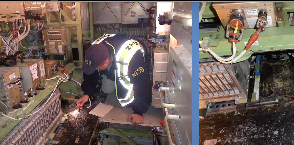
NTSB photo showing the Boeing 787 electrical bay (near
wing) where the battery is lacated after the Logan fire (Jan 7, 2013)
Report states: 10:32 am cleaning crew notices smoke
in cabin.
10:35 am mechanic noted "flames" coming from APU battery
in aft electrical bay.
This is scary as hell. There is electrical equipment
all around the battery.
Engineering perspective
Our company
made power products that sometimes failed. I've been on many teams like
this trying to find the cause. Sometimes the cause is found, sometimes
not. It's not uncommon that everything you can check, i.e. everything not
burned up, is normal, so then you are pretty much stuck. This appears to
be what is happening at Boeing. I know something about batteries and power
electronics. There are basically four pieces to check out here:
1) battery --- cells and how 8 cells are wired in the box (to form a 60
lb, 1.92 kwh, 30V battery)
2) loads --- units where the current out of battery goes
3) charger --- unit that provides the current into battery to charge
it
4) battery protection and monitor circuits --- fuses, cell balancers, fault
circuits (temp, OV, OC, etc)
Good news is that the damage (as far as has been reported) was contained inside the metal battery box that means 2) (loads) and 3) (charger) can be easily checked on the two planes with the fires. Just put in a new battery box and test. This would have been done immediately, and while unreported, nothing must have been found. Also it is unlikely that 2) (loads) are the cause, because the loads are different front and rear of the plane and one fire was in the front battery and the other fire in the rear battery. So no problem in 2) and 3) leaves 1) (battery) and 4) (protection circuits).
The protection circuits clearly failed here. The bad news is that 4) (protection and monitoring circuits) were very likely either fully (or partially) inside the battery box with the cells and got burned up in the fire. Two PC boards are visible mounted inside the box on the side, and in the only picture released they are badly burned. Reports are failure analysis of the failed battery cells and protection PC boards came back with nothing found with the reason given that they were burned up. (No surprise here!) What's left is going to visit the battery manufacturer and PC board maker to review the design and manufacturing quality records.
The latest news is after days of review nothing was found at the battery maker. (Japan regulatory people said that only now are they going start looking at the protection board! Idiots, but I don't doubt that Boeing has had people there for two weeks.)
So what to do? Take the freaking flammable, cobalt lithium ion batteries out of the plane (at least for a while) and replace with the non-flammable type of battery used in hybrid cars, which now have a ten year safety record.
Something like a million hybrid cars are manufactured per year most with a much safer NiMH (nickel metal hybrid) battery. This is three thousand large NiMH batteries manufactured per day (!), and Boeing only needs 100 batteries to re-equip the entire fleet. A hybrid car battery has about the right energy storage, and importantly has an electrolyte (fluid inside) that does not burn. 300V hybrid car batteries could be rewired to put out 30V, peak current should be no problem, new PC boards would be needed for protection. All this is quickly doable. Alternatively, and better from a packaging and maybe regulatory review process, would be to have the battery maker (GS Yuasa) switch over the chemistry in its cells to NiMH (if they have the technology).
The NiMH replacement battery will be about 40 lbs heavier (two boxes replace one box), but so what, bolt the 2nd box to the floor, or ceiling, put it anywhere. The 2nd box will be only a one foot cubed in size. Handle the extra weight (2 x 40 lbs) by telling the airlines to leave one seat empty (Boeing will buy that seat).
Now the engineers
have time to do an in depth safety review of lithium ion batteries. Prof
Sadoway, a battery expert at MIT, has come pretty much to the same conclusion,
saying Boeing is risking the safety of the airplane for the weight of one
suitcase, "it's absurd".
-------------------------------------------------------------------------------------------------------------------------------------------
Update 1/24/13
This is freaking
absurd. The entire fleet has been grounded now something like ten days
(or two weeks) and new planes coming off the Boeing assembly line at a
rapid clip can't be finished and/or commissioned, and the NYT is reporting
this:
"The National Transportation Safety Board indicated Thursday (1/24/13) that an investigation into the failure of lithium-ion batteries aboard two Boeing 787 planes is still far from determining a cause."Prof Sadaway speaks outFailue analysis on one battery yielded nothing cause it's all burned up. Duh !! I presume the charger and inverter, which are physically separate from the battery, were not damaged and have been tested and found to be OK. The plane's black box monitor did not see the voltage go over spec, so that blew a hole in the main failure theory. There's only two failures to analyze, if they haven't found anything by now, it's a good bet they are stuck. Been there on many failure analysis jobs in my business. Often you just can't find anything.
Take the damn lithium batteries out of there
Just take the damn lithium batteries out of there (maybe temporarily, for a year or so). Go the auto manufacturers and get a few dozen hybrid NiMH battery packs, rewire them to get 30V, design up a new little board to interface the sense signals. So it will be a little bigger, hang it from the ceiling, bolt it to the floor, put it somewhere else. It's a battery, it connects up with two wires!
"Another battery expert, Donald Sadoway, a materials chemistry professor at M.I.T., disagreed. He said that sticking with an older type of battery instead of the lighter lithium battery would not have made a huge difference to the 787, adding about 40 pounds, or the equivalent of an extra suitcase per battery. "So you will risk the plane for something that's tantamount to one guy's suitcase?'' Mr. Sadoway said. ''Who's making the calculation here? It's absurd. It doesn't add up.''Cessna fire
With a little digging I found that the Cessna lithium fire in 2011 was pretty serious. It caused a lot of damage to the plane, occurring while the battery was charging from ground power. It was the FAA, not Cessna, that ordered the 44 lb lithium ion battery to be removed and replaced (with NiMH or lead acid) in all 50 of the CJ4's. Cessna was not using a cobalt lithium ion type, its battery was made by 123 Systems, which probably means it was lithium-iron nanophosphate. A123 Systems markets this as more stable and less prone to run away than other types of lithium ion battery.
Counter argument
The counter argument
is that GS Yuasa has been making lithium ion batteries for satellites for
years and has contracts for fifty more satellites. These batteries undergo
rigorous testing and (apparently) have performed well. One person who saw
a GS Yuasa presentation to the military in 2008 said they claimed never
to have had a cell short in ten years of manufacturing. Boeing is big in
the space business so they have in-house guys who should have had long
experience with, and a good understand of, these batteries.
And of course, there must have been a driving dynamic (pressure) inside Boeing when designing the new 787, a composite filled new high milage plane, to take risks, to learn to master new technology, design for minimum weight. It would be a hard sell in engineering meetings to argue the fire risk of the cobalt high energy density cells could not be mitigated, expecially when it was being proposed for aviation use by an experienced battery builder in a rugged sealed (sort of) case. And someone would probably say, this is what plane design is all about, the wings and belly of a plane are full of tons of flammable fuel, yet due to good design the risks are very, very low.
Spec review
I printed
out the GS Yuasa data sheet for the Boeing cell and for related 8 cell
industrial version they manufacturer. Their 8 cell industrial version is
mounted in plastic matrix case, weighs 44 lbs, has an Ah rating of 30A
(vs 65A for the Boeing), but is rated for higher current discharge and
much higher current charge. GS Yuasa cools their 8 cell battery pack with
two muffin fans. Looking at the curves I find the cell ESR for the Boeing
cells is 0.8 mohm and the ESR for the whole GS Yuasa battery pack is 1
mohm, so each cell's ESR is about x6 lower than Boeing (1/2 energy, but
much lower ESR).
27 W in box at charge -- no problem
The max charge current
for the Boeing cell is low (1C or 65A) vs 600A for the industrial version.
This calculates for the Boeing cell to a maximum cell ohmic loss of 3.4W/cell
or 27 watts (for one hour) in the whole box. This is fine and totally consistent
with no cooling for the box. (The Boeing cell is speced for a maximum discharge
current of 325A (5C or 12 min), but I have no idea as to what the actual
discharge current is.)
I note all cells have rupture release plates. This is to prevent an explosion, but it would allow flammable electrolyte to get into the box, and it looks like this is what happened. The cells are contain the damage from a fault, but clearly did not.
The Boeing
cell has screw terminals. I wonder if the failure is something as simple
as overtorquing of the cell terminals causing over time an internal cell
short. On the other hand you would think a plane builder would be as expert
as anyone can be in assembling things!!
------------------------------------------------------------------------------------------------------------------------------
Boeing battery info
(update 1/22/13)
I got the
battery voltage right and weight right. Today a NYT article lists the max
voltage (charging) as 32 V and the Boeing battery box was mentioned as
being 63 lbs (I guessed 60 lbs, since the 8 cells weighed 48 lbs).
"In Washington, the National Transportation Safety Board said on Sunday that the battery on a Japanese plane that suffered a fire at a gate at Logan airport in Boston on Jan. 7 had not been charged beyond its maximum design voltage, 32 volts."News stories indicate at least one of the battery voltages is recorded by the flight data recorder, and it shows that on Japanese plane the battery voltage was (apparently) normal (specifically it didn't exceed 32V max spec). Also read the flight recorder on the Boston plane did not show voltage above 32V.
Two other names popped up today, company that designed the electronics associated with the battery and the company that designed the battery charger:
"The electrical system into which the battery is embedded (other articles imply thay make the inverter that steps up the 30V) is manufactured by Thales, Europes biggest defense- electronics maker."Get this!!!"Securaplane Technologies Inc., manufacturer of the charger for the 787s lithium ion batteries, at the company's headquarters in Tucson, Arizona, said Kelly Nantel, a spokeswoman for the board."
"Securaplane (designer of the Boeing battery charger), a unit of Britain's Meggit, first began working on the charger in 2004, but suffered millions of dollars of damages in November 2006 after a lithium-ion battery used in testing exploded and sparked a fire that burned an administration building to the ground." (Reuters)Looks like a long history of Boeing and GS Yuasa (battery manuf)
(http://www.reuters.com/article/2013/01/21/us-boeing-securaplane-idUSBRE90J0B320130121)
"GS Yuasa gets about 42 percent of sales from outside Japan, selling lead-acid batteries for forklifts and other machines in countries such as China and Thailand. The company first demonstrated its technology in a prismatic lithium-ion battery in 1993 and won its first order from Boeing in 2005. A unit of GS Yuasa won a contract in August to supply lithium-ion battery cells to the international space station. Boeing oversees all contract work at the space station as NASAs prime contractor."The grounding of the plane must be having a huge effect on the Japanese airline that owns most of the Dreamliners.
" ANA to cancel 141 flights between Wednesday and Sunday, affecting more than 18,000 passengers."-----------------------------------------------------------------------------------------------------------------------------------
Even scarier is this: It is reported (see below) that during flight tests of the plane during its development, there was a battery fire that required an emergency landing and slides to be used. This would seem to indicate that the fire hazard with the cobalt lithium ion batteries is real and has been long known at Boeing. Boeing exec were reported to have been passengers on the development flight with the fire, so the battery problem is probably pretty well known within Boeing.
The batteries are about the size of the battery in a hybrid car. Each is a metal box about one foot cubic, weighing 60 lbs or so, with inside eight sealed lithium ion cells wired in series. This is a low voltage battery pack [29.6V = 8 x 3.7V] rated at 65 A-hr, which gives an energy rating of [65A-hr x 29.6V = 1.92 Kwh]. These are lithium ion cells, but not the type usually used in hybrid and electric cars. Boeing is using cobalt lithium ion, which are more expensive with about double the energy density of cells used in cars, thus cutting the weight of the battery. In my battery essay I had noted about cobalt cells only that they were considered to be more 'explosive'. Posters are saying cobalt lithium ion cells are prone to fire if they get too hot.
I learned when researching batteries for my battery essay that the lithium salt used an the electrolyte (LiPF6) cannot be dissolved in water as lithium (group 1 element) reacts strongly with water yielding hydrogen gas, so the lithium salt is dissolved in a non-aqueous organic solvent. An 'organic' solvent means it is a hydrocarbon, hence the electrolyte in a lithium ion battery is flammable.
My first thoughts
My first though
is take the damn lithium ion batteries out and replace with NiMH. These
are made by the hundreds of thousands for hybrid cars. Boeing only need
a few dozen. So they will be a little bigger and weigh more, leave on seat
unsold. Peak power should be no problem as these are used in hybrid cars,
they are designed for this, and a car battery pack would come with protections
built in. Then the Boeing engineers would have the time, a year or so,
to really figure out lithium ion batteries and what went wrong here and
how to fix it.
A poster says the Boeing battery is LiCo (lithium cobalt) and claims this type of lithium ion battery is is famous for "venting with spontaneous combustion. Another article on a site calls 'ArsTechnica' appears to confirm the poster:
"The batteries at the heart of the problem, manufactured by the Japanese firm GS Yuasa Corporation, are essentially giant versions of the lithium-ion batteries used in cell phones and laptops. Like those batteries, the Dreamliner's use a lithium-cobalt oxide cathode, which is "an inherently unsafe cathode," said Mark Allen, assistant professor of chemistry and biochemistry at the University of Maryland, Baltimore County. And in the larger form used by Boeing, they pose an even larger risk. When overcharged or damaged, they can become essentially a firebomb inside the airplaneone that burns without air and can't be put out by usual aircraft fire suppression systems."This article details a serious battery fire that took down the flight control system during flight with Boeing execs as passengers. They had to evacuated after an emergency landing using slides.
"The Dreamliner's batteries, however are not your garden-variety laptop battery. Manufacturer GS Yuasa started in the business making motorcycle batteries and now makes large-scale specialty batteries for all sorts of power applicationsincluding powering satellites. The batteries selected for the Dreamliner "were very large scale65 amp-hour batteries which is very, very large," said Allen. "They are very high power batteries, and they charge them to 90 percent (of capacity) in about 70 minutes. That's a very fast charge for any lithium battery of this size. And that's a problem when there isn't a cooling system incorporated."-----------------------------------------------------------------------------------------------------------------------------------------------------------------------------------"The problem escalates as the battery gets hotter. "When these batteries reach a certain temperatureabout 140 degrees Celsiusthey reach a thermal runaway where they basically go out of control," Allen said. And that can turn the batterythe one in a plane, or the one in your cell phoneinto a firebomb."
"There are a number of fixes Boeing could make to reduce the risk from the batteries. One is to use batteries with a cooling systemeither water or air cooling."
"But there are also much safer choices for the cathode material in large lithium batteries that can reduce the risk of explosive combustion. Allen hopes that the Dreamliner issues will lead to wider adoption of safer battery technology." They are available and becoming more popular," Allen said. "Lithium nickel manganese oxide cathodes are safer, and iron phosphate ones are much safer because they don't actually release oxygen when you arc it or when it's damaged."
"An assessment by international consultancy Lux Research notes that even among lithium-ion batteries types, Boeing could have picked a safer alternative with little loss of performance. The 787s batteries use lithium cobalt oxide (LCO), a material that imparts excellent energy density but does not resist overheating well. Once started, lithium-ion fires typically generate oxygen, making them difficult to extinguish. In the first case of battery failure, aboard a Japan Air Lines 787 parked at Boston Logan Airport, firefighters needed 40 minutes to put out the resulting fire."-------------------------------------"In choosing LCO, Boeing eschewed safer alternatives such as lithium-iron phosphate (LFP), according to Lux. Even when overcharged, LFP changes only slightly in structure, it noted, preventing oxygen release and resisting the repeating cycle of heat generation known as thermal runaway. This decision is all the more shocking considering major automakers early on refused to entertain the possibility of using LCO in passenger vehicles due to safety concerns, said the Lux report." (1/21/13)
http://www.ainonline.com/aviation-news/ain-air-transport-perspective/2013-01-21/ntsb-finding-adds-wrinkle-787-battery-prob
manuf
GS Yuasa
cell model #
LVP 65 (prismatic form factor, sealed)
Kwh rating
1.92 Kwh = 29.6V x 65 A-hr
(8 x 3.7V, 65 A-hr cells in series)
energy density
101 Wh/kg (3.7 v x 75 (nom) Wh/2.75
kg (per cell) = 101 Wh/kg)
discharge current
375 A max =(5 x 75A or 5C) (50
- 250 A in curves)
ESR
0.75 mohm = (0.15V/(250A - 50A)) from curves, 0.3 mohm AC (table)
SS (calculated)
4,900A = (3.7V/0.75 mohm)
charge
0 to 90% in 75 minutes
charge current
75A
chemistry
Lithium cobalt oxide (cathode)
physical size
17 in x 11 in x 8.5 in (1 ft cube box from poster)
cell size
7.0 in x 5.2 in x 1.97 in (178 mm x 132 mm x 50 mm)
weight
6 lb/cell or (48 lb for 8 cells) (63 lb for Boeing's metal box with 8 cells)
location
(front) beneath cockpit and (rear) electrical bay near wing
battery system electronics
Thales Alenia
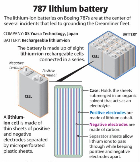 .
. 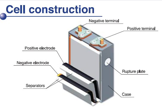
Notice 'rupture plate' on side of cell.
This is designed to blow out to prevent a dangerous
pressure build up inside (and possible explosion) if the electrolyte should
get too hot and vaporize.
(GR Yuasa @ http://twinkle_toes_engineering.home.comcast.net/~twinkle_toes_engineering/battery_spec_boeing_cobalt_lithium_ion_boeing_787_cell_LVP10-65.pdf)
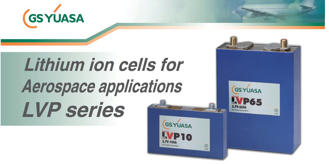
source (left) --- http://seattletimes.com/ABPub/zoom/html/2020162341.html
(LVP 65 --- 3.7V, 65A-hr, 6 lb (2.75 kg) cell)
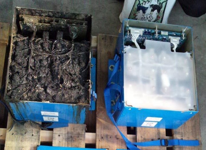
burned lithium ion battery removed from Boeing 787
in Japan
Clearly all eight cells are burned up, and the fire
destroyed too the PC boards (top) with monitoring and control circuits.
(photo provided by the Japan Transport Safety Board)
source --- http://seattletimes.com/ABPub/zoom/html/2020162341.html
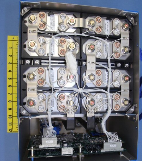 .
. 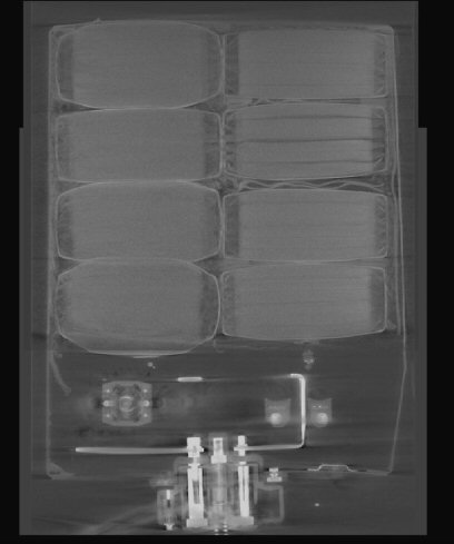
Thales designed Boeing 8 cell, 30V x 75 Ahr, 64 lb
lithium ion battery
Cells virtually touching ('can you say packed'), PC
control boards inside, thin sheet metal outside box
(source --- NTSB interim report http://www.ntsb.gov/investigations/2013/boeing_787/JAL_B-787_1-24-13.pdf)
Energy density update (1/24/13)
In reading
about lithium ion batteries I find the spec of the GS Yuasa cobalt lithium
ion battery is not all that high. The GS Yuasa battery is speced (nom)
at 101 Wh/kg. A recent article about lithium ion batteries for aviation
(many for model planes) and most cobalt said 130 to 160 Kw/kg was common
and some batteries are pushing toward 200 Wh/kg. Some of the difference
might be that for Boeing the battery and its case were ruggized aviation
use. For a check I calculated the energy density for a small cylinderical
A123 cell spec decribed in this essay. Result was 3.3V x 2.3 Ah/0.07 kg
= 108 Wh/kg.
--------------------------------------------------------------------------------------------------------------------------------------------
Flight data recorder data for Boston fire (3/8/13)
Here is an
email summary (sent to engineering friends) of the battery voltage and
current plots as the fire begins:
You might be interest in this. I've been following the Boeing battery problem closely since the beginning. The NTSB accident report released last week had 500 pages of data attached, which the press ignored. I dug through it and found attached. It is the plane data recorder for the Boston battery fire showing plot of battery voltage and current as the battery fails. It is consistent with one cell beginning to burn.------------------The battery is just sitting there a few minutes after landing apparently fully charged (32V) doing basically nothing! The APU (aux power turbine in tail) was started when plane landed and is running. The battery powers the APU controller circuit. This is a very light load on the battery (0 to 1A), which is nothing for a battery rated at 75A for an hour.
The data shows the voltage suddenly starts to fall a volt or so from 32V [8 x (3.7 to 4V) cells in series]. In a few seconds the charger responds with 44A into the battery, my guess is this is the normal range for charging current since the cells are rated for 65A max charge current. After a few seconds, the charger apparently detects something is not right and shut off the charging current and six seconds later a battery failure signal appears. 20 to 30 seconds later the battery voltage falls to 28V (one cell is shorted) and then to zero, which is either the burned cell burning open or possibly the contactor in the battery opening.
The APU we now find out can't run with a dead (rear) battery so it shuts off leaving the plane with no power (except for front battery which can only power the cockpit). The fire was first detected by someone in the cockpit who noticed the power in the plane just shut off. The cabin then filled with caustic smoke because the venting system of the plane failed since we now find out that it depends on powered valves and when the battery took the APU down there was no valve power. Whoops!
Very odd battery failure, no obvious trigger, very worrying. This plane was brand new, had only gone into service a couple of weeks before the fire.
The data below shows the battery was (probably) just sittting there doing nothing, the current was nearly zero (1A out). Then the voltage falls a volt or so and for a few seconds 44A flow into (says report) the battery. It would seem logical that this is the charger responding to a drop in battery voltage, but after a few seconds the charger senses that something is not right and shuts off. Don't know what normal charge current is but I can believe 44A is in the normal range. The max charge current of the cell is 1C or 65A, so setting max charge current at 2/3rd of the cell spec would seem reasonable. And at 44A the ESR heating in each cell (0.75 mohm) would be only 1.4W or 11W for the whole battery which is fine.
Caveat on current plot
There is an unfortunate confusion in the report about the current. The plot labelling would seem to indicte this is the current read at the BATTERY, there is a hall current sensor inside the battery, but the text describing the plots says it is the current is measured at the CHARGER! (Don't have data on the charger, but it would likely that it does have a current sensor.) It is unlikely that the charger would input (much current), so since the current plot goes both positive and negative I think it is more likely than not that this is the battery current.
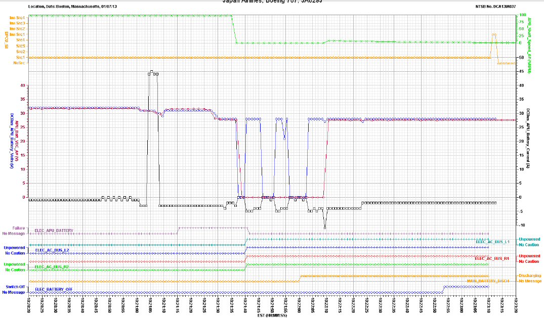
Key data (from above): Current is nearly zero (1A out)
PRIOR to the event with voltage at 32 volts (presumably showing battery
near fully charged).
This shows the battery is just sitting there doing
pretty much nothing when it catches on fire!
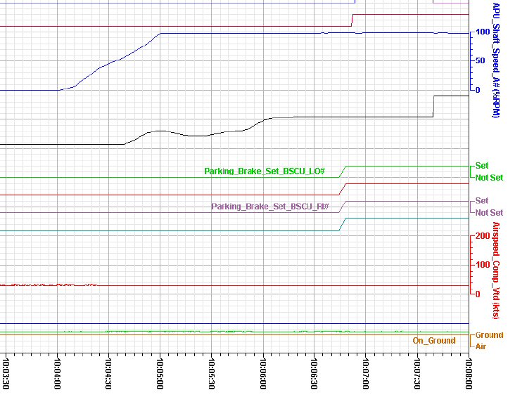
blue shows it takes about 1 min to start the APU
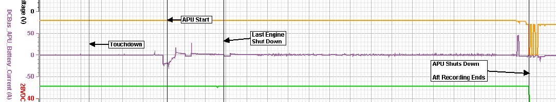
glitches on far right of this plot show the battery
failing
left shows the battery current drain during APU start
(1 min or so with engines running) is only about 20A
--------------------------------------------------------------------------------------------------------------------------------------------
Links
Burned battery pic (from Japan plane)
http://seattletimes.com/ABPub/zoom/html/2020162341.html
Cobalt lithium ion battery data sheet
(type used on Boeing plane)
http://www.s399157097.onlinehome.us/SpecSheets/LVP10-65.pdf
Good background technical article (discussed
fire during development)
http://arstechnica.com/business/2013/01/boeings-dreamliner-batteries-inherently-unsafe-and-yours-may-be-too/?comments=1&start=40
=================================================================================